Synchronous movable storage device

A technology for synchronously moving and storing devices, applied to instruments, coin-operated equipment for distributing discrete items, coin-free or similar appliances, etc., can solve problems such as low space utilization, low economic benefits, improper operation of personnel, etc. Achieve the effects of convenient access, wide application range and high space utilization

Active Publication Date: 2018-10-02
SHANGHAI UNIV OF ENG SCI
View PDF10 Cites 0 Cited by
  • Summary
  • Abstract
  • Description
  • Claims
  • Application Information

AI Technical Summary

Problems solved by technology

However, there are many disadvantages in temporary storage devices in many public areas: ①The number of storage cabinets is too small, especially in large public places. nowhere to put
However, it is obvious that the space utilization rate is low and the economic benefit is low.
② The storage cabinets are accessed by the customers themselves, and the height of the cabinets randomly assigned by the system is also random. Therefore, cabinets located too high are extremely inconvenient for the disabled or the elderly
③Traditional lockers must close the door consciously after picking up the items, otherwise it will affect the use of subsequent customers. Once personnel operations are involved, there will inevitably be problems of improper operation of personnel
④Customers’ self-storage, self-collection, and walking around each other, especially when the flow of people is too large, will cause congestion and confusion, which will also affect access efficiency and even pose safety hazards

Method used


Image

  • Synchronous movable storage device
  • Synchronous movable storage device
  • Synchronous movable storage device

Examples


Embodiment Construction

[0023] The preferred embodiments of the present invention will be described in detail below in conjunction with the accompanying drawings, so that the advantages and features of the present invention can be more easily understood by those skilled in the art, and the protection scope of the present invention will be defined more clearly.

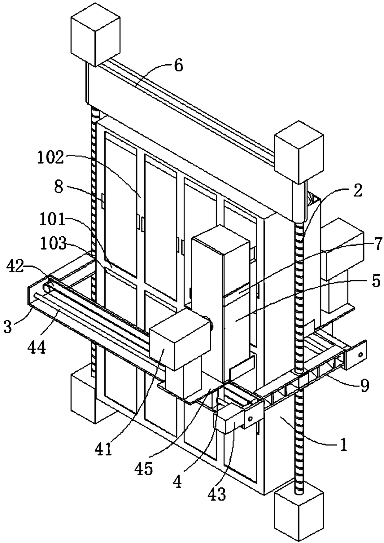
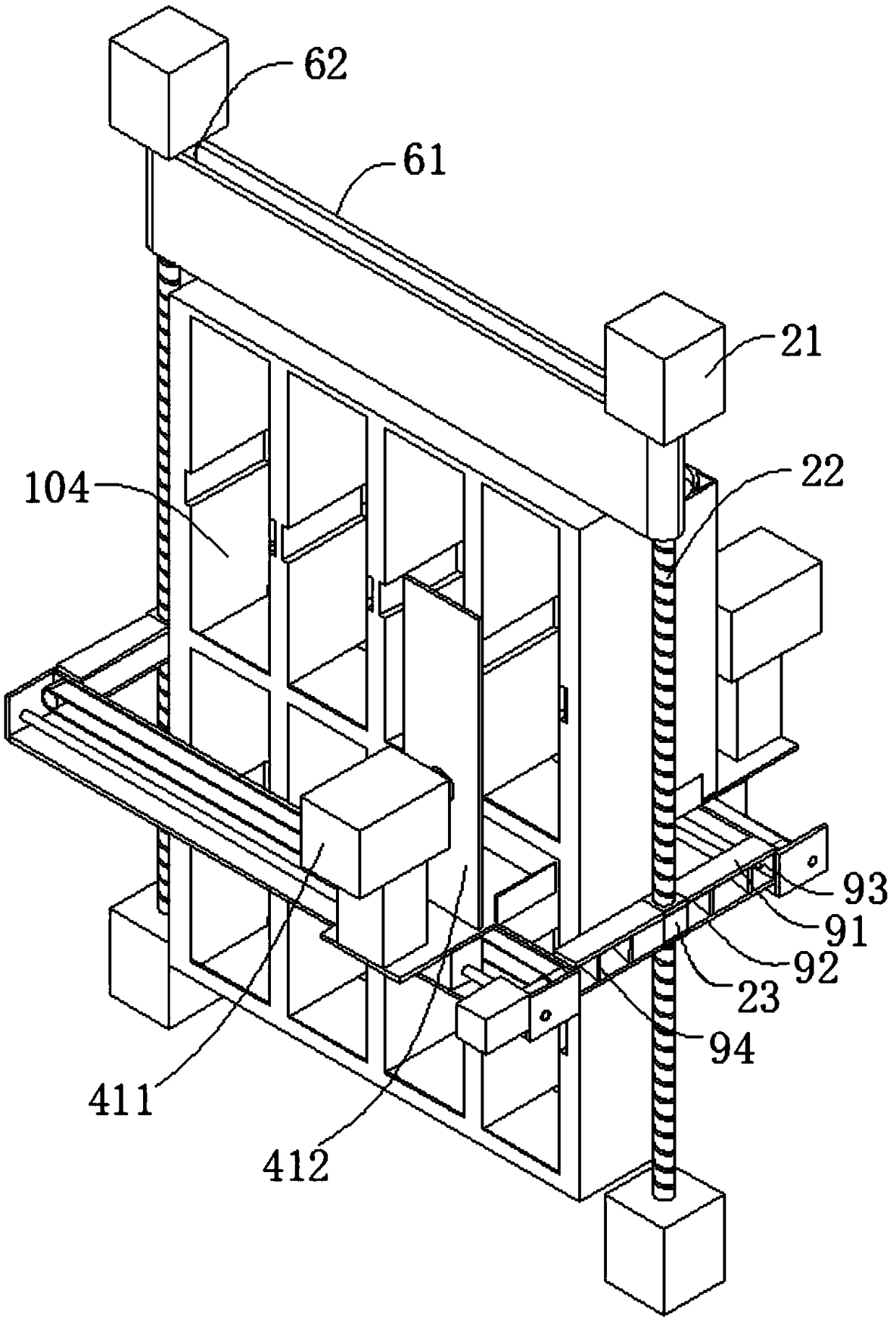
[0024] See Figure 1-2 As shown, the synchronous mobile storage device of the present invention includes:

[0025] A rectangular storage shelf 1 is composed of a plurality of horizontal plates 101 and a plurality of vertical plates 102 staggered to form a plurality of rows and columns of rectangular storage cavities 103, each of the storage cavities 103 has openings 104 on both front and back sides;

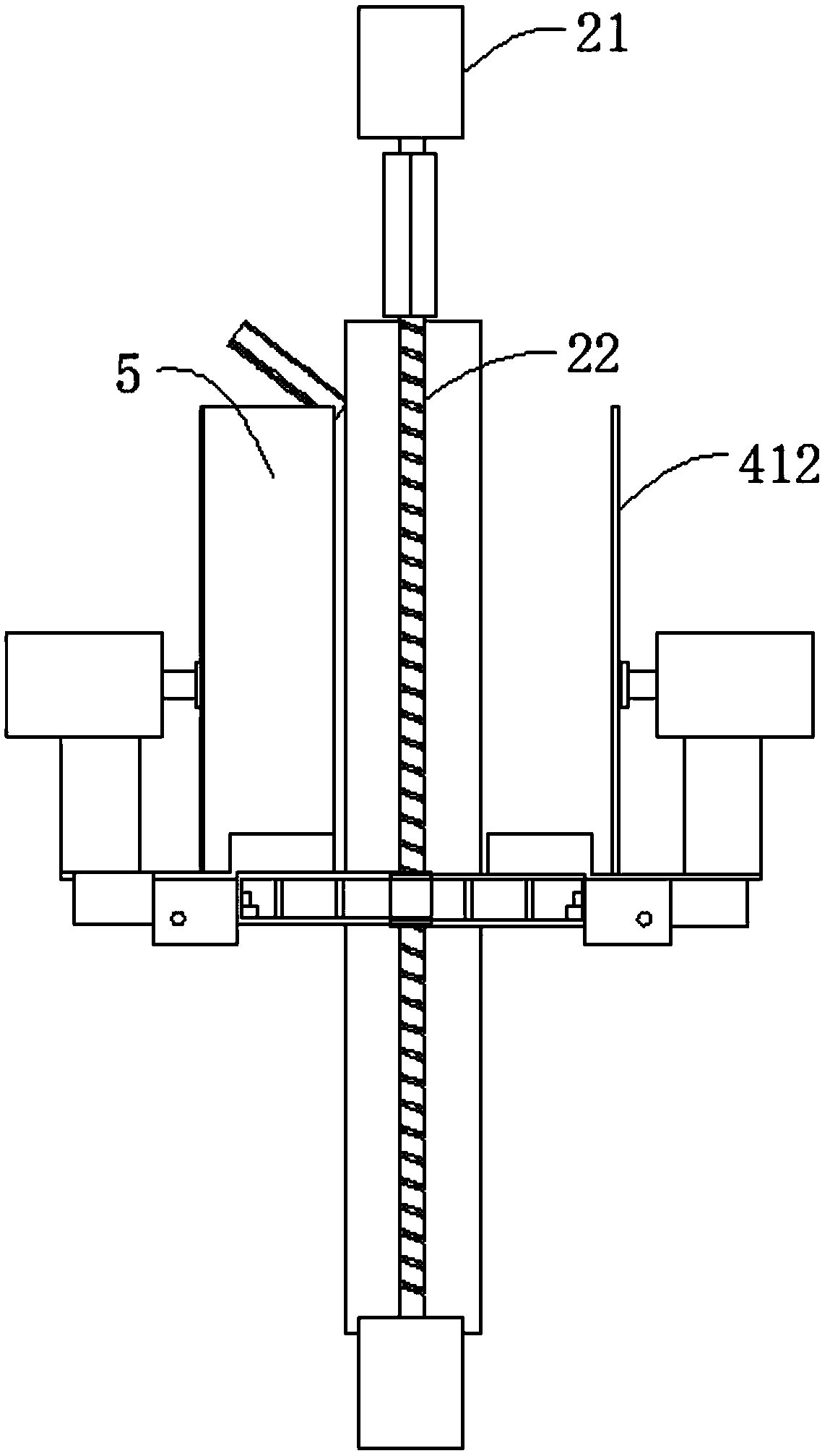
[0026] On the front and rear sides of the storage rack 1, a horizontal bracket 3 that can be moved up and down driven by the vertical drive mechanism 2 is respectively provided. The horizontal bracket 3 is equipped with a horizontally movable push tabl...


PUM


Abstract

The invention discloses a synchronous movable storage device which comprises a rectangular storage rack. A plurality of transverse plates and a plurality of vertical plates are staggered to form a plurality of rectangular storage cavities in multiple rows and multiple columns, and openings are formed in the front side and the rear side of each storage cavity; horizontal brackets which can be driven by vertical driving mechanisms to move in the up-down directions are arranged on the front side and the rear side of the storage rack, push tables which can horizontally move are configured on the horizontal brackets and can move to the storage cavities at optional row and column locations, and movement in the up-down directions and horizontal movement refer to two-side synchronous movement; a storage box is arranged on the push table on a side of the synchronous movable storage device and can be pushed into the corresponding storage cavities by a push mechanism of the push table, the push table on the other side of the synchronous movable storage device is idle, corresponding replaced front storage boxes can be received by the push table on the other side of the synchronous movable storage device, and every two corresponding ends of the two horizontal brackets are fixedly connected with each other by a connecting rod. The synchronous movable storage device has the advantages of highspace utilization rate, access convenience and wide application range.

Description

Technical field [0001] The present invention relates to the technical field of storage devices, in particular to a synchronous mobile storage device. Background technique [0002] In today's era, with the changes in consumption structure, the storage of goods is no longer as primitive stacking or simple classification as in the past. A variety of goods must be stored in a reasonable way, especially in densely populated areas. However, many temporary storage devices in public areas now have many disadvantages: ①The number of storage cabinets is too small, especially in large public places. Customers often encounter that the storage cabinets are full and it is inconvenient to bring their own things in. Nowhere to put it. However, the space allocated for storage cabinets is obviously low in space utilization and low economic benefits. ② The storage cabinets are accessed by the customers themselves, and the cabinets randomly assigned by the system are also random. Therefore, cabine...

Claims


Application Information

Patent Timeline
IPC IPC(8): G07F17/12
CPCG07F17/12
Inventor 费桂义严平顾一飞
Owner SHANGHAI UNIV OF ENG SCI
Why Eureka
Try Eureka