
Driver box body structure

A box structure and driver technology, which is applied in the direction of electric components, casings/covers/supports, electrical components, etc., can solve the problems of many parts of the push rod driver, insufficient self-locking function of the driver, hidden dangers of rotor bearing movement, etc. Achieve the effect of preventing axial movement, ingenious design, and reducing assembly processes

Pending Publication Date: 2018-10-02
DEWERTOKIN TECHNOLOGY GROUP CO LTD
View PDF0 Cites 1 Cited by
  • Summary
  • Abstract
  • Description
  • Claims
  • Application Information

AI Technical Summary

Problems solved by technology

[0006] The purpose of the present invention is to provide a driver box structure to solve the technical problems of the existing push rod driver with many parts, complicated assembly process, easy damage to the carbon brush during the assembly process, potential movement of the rotor bearing and insufficient self-locking function of the driver

Method used


Image

  • Driver box body structure
  • Driver box body structure

Examples


Embodiment Construction

[0022] Below in conjunction with accompanying drawing, the present invention will be further described:

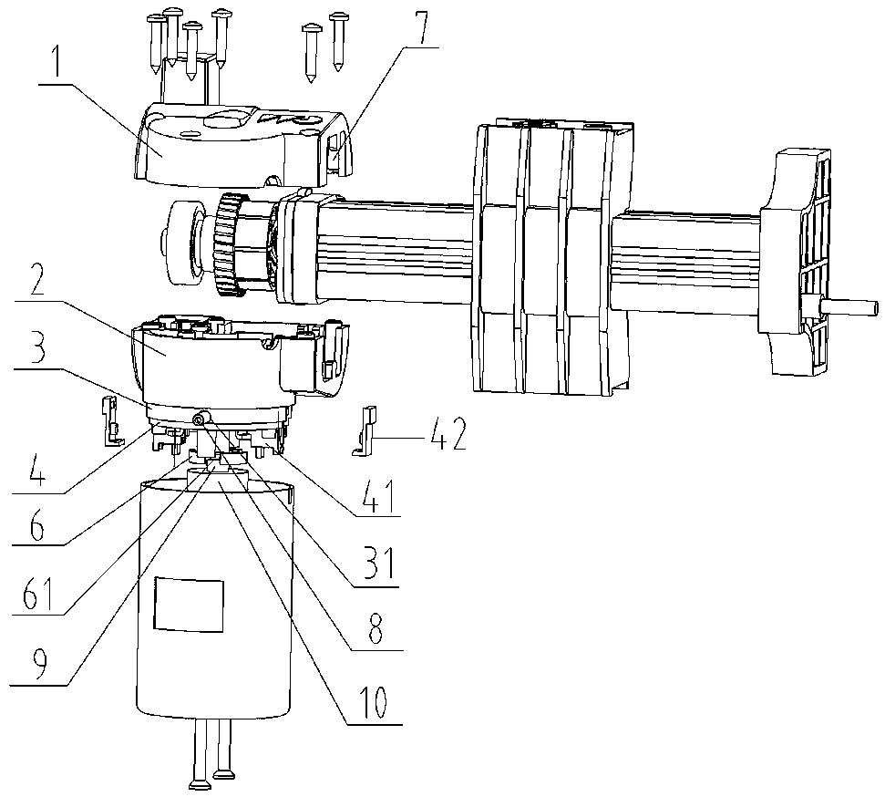
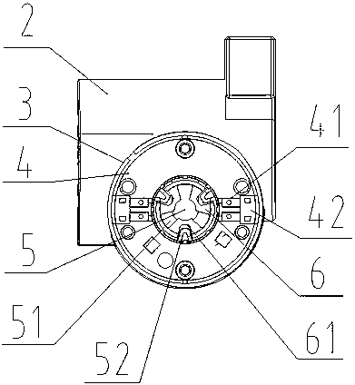
[0023] Such as figure 1 and figure 2 As shown, a driver box structure of the present invention includes an upper driver box 1 , a lower driver box 2 , a motor front cover 3 , a motor brush holder plate 4 and a damping member 6 . The motor front cover 3 is arranged on the lower box body 2 of the driver. The motor front cover 3 is provided with a motor brush holder plate 4, and two screw holes 31 are provided symmetrically on the side. Two brush holders 41 are symmetrically arranged on the motor brush holder plate 4 , and a through hole 5 is arranged in the center. The front and rear ends of the brush holder 41 are open and connected to each other. The brush holder plug 42 cooperates with the brush holder 41 and is detachably connected with the brush holder 41 . A limiting step 51 is arranged in the through hole 5 , and three bosses 52 are arranged on the limiting step...


PUM


Abstract

The invention discloses a driver box body structure. The driver box body structure comprises a driver upper box body, a driver lower box body, a motor front end cover and a motor brush rack plate, wherein the motor front end cover is arranged on the driver lower box body, the motor brush rack is arranged on the motor front end cover, a screw hole is formed in a side surface, a brush handle is arranged on the motor brush rack plate, a through hole is formed in the center, openings are formed in a front end and a rear end of the brush handle and communicate with each other, a limitation step isarranged in the through hole, a boss is arranged on the limitation step, and the driver lower box body, the motor front end cover, the motor brush rack plate and the brush handle are integratedly formed. By the driver box body structure, the matching accuracy of the driver box body and the product consistency are improved, the assembly process is reduced, and the cost is reduced; the openings areformed in the two ends of the brush handle, a rotor is pressed during assembly, a carbon brush is arranged, and the carbon brush is prevented from being damaged; a rotor bearing is reinforced by the formed screw hold matched with a screw, and the bearing is prevented from axially moving; and the automatic locking function of a driver is improved by a damping piece, and the problems that a large-range driver having the automatic locking function is high in cost and is easy to damage are solved.

Description

technical field [0001] The invention belongs to the technical field of drives, and in particular relates to a drive box structure. Background technique [0002] The existing push rod driver is assembled from components such as a rotor assembly with a worm, a brush holder plate assembly, a front end cover, a rear end cover, a worm gear transmission assembly, a box body, a box cover, and an aluminum alloy guide rail. The brush holder plate assembly is installed on the front end cover by means of screws or riveting, and the connection between the brush holder and the brush holder plate is also by means of screws, riveting or clamping. After the front end cover, rear end cover, and casing are assembled into a motor, they are then assembled on the box body with screws; the brush holder is installed separately and requires a matching brush holder frame. Such a structure has poor matching accuracy, low product consistency, and the assembly process Complicated and consumes a lot of...

Claims


Application Information

Patent Timeline
Patent Type & Authority Applications(China)
IPC IPC(8): H02K5/04H02K5/14H02K5/16H02K5/22
CPCH02K5/04H02K5/14H02K5/163H02K5/22
Inventor 雷陈建李龙朱浩翔
Owner DEWERTOKIN TECHNOLOGY GROUP CO LTD
Learn More