A plug-in device for preventing continuous casting slab tail billet from rising and its application method

A plug-in device and continuous casting slab technology, applied in the field of continuous steel casting, can solve the problems of production logistics and steelmaking capacity impact, short pouring length, equipment loss, etc., achieve high automation, increase liquid steel space, and prevent inflation Effect

Active Publication Date: 2020-03-06
BAOSHAN IRON & STEEL CO LTD
View PDF13 Cites 0 Cited by
  • Summary
  • Abstract
  • Description
  • Claims
  • Application Information

AI Technical Summary

Problems solved by technology

All these accidents not only caused great losses on equipment, but also had a great impact on production logistics and steelmaking capacity.
Most of the rising accidents faced by thick plate continuous casting now occur in some abnormal situations, such as the submerged nozzle being broken at the same time, the slag under the tundish, etc., and a large part of it is because the pouring length is relatively short, basically less than 15 meters. The reason is that the liquid The core is relatively short, and the molten steel billet shell cannot reach a balance with the solidification shrinkage of the molten steel and the amount of molten steel squeezed out under light pressure, so that the molten steel flows out from the edge of the billet shell
In the continuous casting of the current technology, these abnormal situations are dealt with by capping with nail chips, which is basically useless for large sections with specifications such as 2300mm*300mm

Method used


Image

  • A plug-in device for preventing continuous casting slab tail billet from rising and its application method
  • A plug-in device for preventing continuous casting slab tail billet from rising and its application method
  • A plug-in device for preventing continuous casting slab tail billet from rising and its application method

Examples


Embodiment Construction

[0029] The specific implementation manners of the present invention will be described in detail below in conjunction with the accompanying drawings of the embodiments.

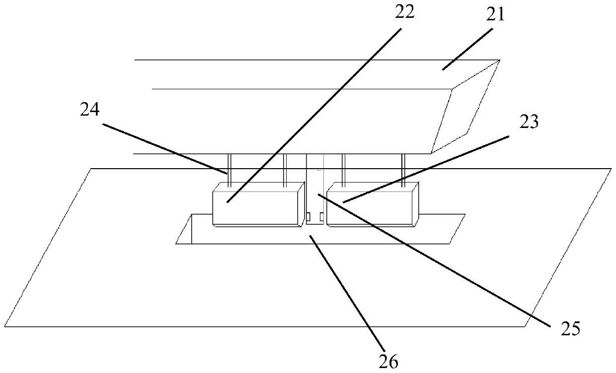
[0030] See figure 2 , which consists of two plug-ins and four landing gear connecting rod mechanisms.

[0031] The two inserts include a left insert 22 and a right insert 23, the left insert 22 and the right insert 23 are respectively installed on the tundish trolley lifting support frame 21 through two respective landing gear connecting rod mechanisms 24, and respectively Placed on both sides of the submerged nozzle 25 of the tundish, the trolley lifting support frame 21 is located at the bottom of the tundish.

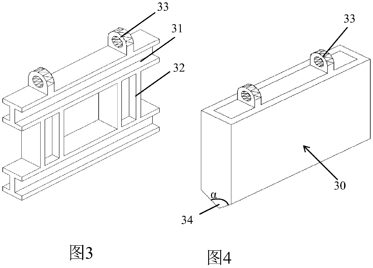
[0032] The left side plug-in 22 and the right side plug-in 23 have the same structure, and are collectively referred to as plug-in 30, as image 3 As shown, the inside of the plug-in 30 is a rectangular keel frame formed by welding structural steel; the keel frame is composed of two I-beams 31 and...


PUM

PropertyMeasurementUnit
lengthaaaaaaaaaa
heightaaaaaaaaaa
thicknessaaaaaaaaaa

Abstract

The invention discloses an inserting part device for preventing a tail billet of a continuous casting billet from rising and a use method thereof. The inserting part device comprises two inserting parts and four lifting frame connecting rod mechanisms, wherein the two inserting parts include a left side inserting part and a right side inserting part which are correspondingly mounted on a tundish trolley lifting supporting frame through two corresponding lifting frame connecting rod mechanisms; the left side inserting part and the right side inserting part are structured the same and are both named inserting parts; two mounting rings are fixedly welded to the top part of each inserting part; the four lifting frame connecting rod mechanisms are structured the same and are correspondingly connected to four mounting rings on the two inserting parts; each lifting frame connecting rod mechanism comprises an inserting part connecting rod, a thrust oil cylinder, a fixing frame and an oil cylinder connecting rod which are interconnected through hinge structures; and the fixing frames are fixed to the tundish lifting trolley supporting frame through bolts. The device is high in reliability of preventing rising, and is high in automatic degree of operation; and a continuous casting machine can be effectively protected.

Description

technical field [0001] The invention relates to the field of continuous steel casting, in particular to a plug-in device for preventing continuous casting slab tail bulging and its use method for preventing the casting of wide and thick slab continuous casting machines from bulging accidents. Background technique [0002] The special steel requirements for wide and thick plates must require the use of light reduction methods in continuous casting production (such as figure 1 shown), the so-called light reduction means that in order to improve the occurrence of center looseness and center segregation when the continuous casting slab is solidified, an appropriate reduction amount is added to the slab 11 at the slab solidification end 12, so that the solidification end segment roll It is a means to reduce the gap (referring to the distance between the rollers on the sector, that is, the appropriate reduction of the roll gap value). The internal defects such as segregation of t...

Claims


Application Information

Patent Timeline
Patent Type & Authority Patents(China)
IPC IPC(8): B22D11/16B22D27/11
CPCB22D11/16B22D27/11
Inventor 张林权姜立新任以平
Owner BAOSHAN IRON & STEEL CO LTD
Why Eureka
Try Eureka