
Paper cup collecting device for forming machine for paper cup provided with handle

A collection device and forming machine technology, applied in packaging, packaging protection, transportation and packaging, etc., can solve the problems of unfavorable automatic packaging stacking, loose paper cup tubes, easy to fall, etc., to achieve convenient transportation stacking, compact stacking, and reduce labor intensity effect

Pending Publication Date: 2018-10-09
京山大昌商贸股份有限公司
View PDF1 Cites 0 Cited by
  • Summary
  • Abstract
  • Description
  • Claims
  • Application Information

AI Technical Summary

Problems solved by technology

[0003] The purpose of the present invention is to aim at the present, in order to prevent hot hands, a handle will be pasted on the cup wall of the paper cup, the middle of the handle will be pasted on the cup wall, and the two ends of the handle are movable ends. There is a certain gap, and the handle can be used as a handle by folding the two ends of the handle together when using it. China Patent Network CN103317776B has announced a "suction and release double paper mechanism of sticky handle type paper cup forming machine", which is used for one-time production. After the paper cups are formed, due to the existence of the handle, the gap between the paper cups is large when the paper cup forming machine collects the paper cups, making the paper cup tubes loose and easy to fall, which is not conducive to automatic packaging and stacking. It is necessary to manually press the stacked paper cup tubes Insufficient stacking in the end, but provide a paper cup collection device for the cup paper cup forming machine

Method used


Image

  • Paper cup collecting device for forming machine for paper cup provided with handle
  • Paper cup collecting device for forming machine for paper cup provided with handle

Examples


Embodiment Construction

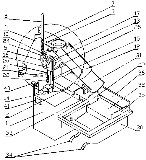
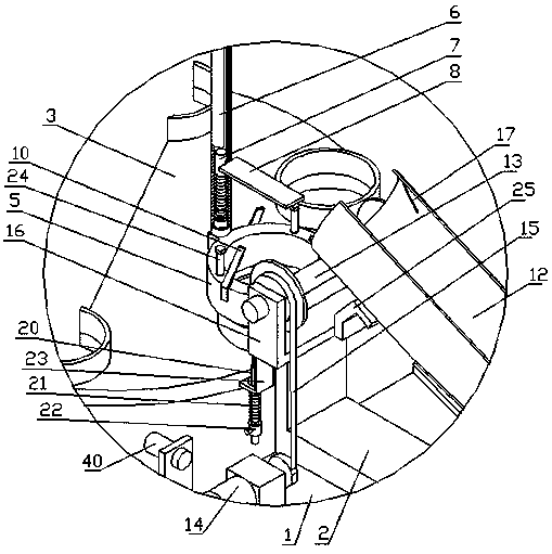
[0009] As shown in the drawings, the present invention includes a base 1, a cylindrical cup holder 5, a guide cylinder 6, a guide rod 7 and a pressure plate 8. The cylindrical cup holder 5 is installed on the base 1 through a support frame 2, and is located Above the discharge tray 3 of the machine, there are a plurality of first elastic stoppers 10 in an annular array on the top of the cylindrical cup holder 5, and the movable ends of the plurality of first elastic stoppers 10 move towards the center of the cylindrical cup holder 5 respectively. The top of the cylindrical cup holder 5 is provided with a guide cylinder 6 connected to the screw rod. One end of the guide cylinder 6 is provided with an internal thread. The guide cylinder 6 is screwed on the cylindrical cup holder 5. In the cylinder 6, the side wall of the guide cylinder 6 is provided with a pressure plate 8 movable escape port, one end of the pressure plate 8 is installed on the guide rod 7, and the other end of t...


PUM


Abstract

A paper cup collecting device for a forming machine for a paper cup provided with a handle comprises a base (1), a barre-shaped cup positioning rack (5), a guide barrel (6), a guide rod (7) and a pressing plate (8), wherein the barrel-shaped cup positioning rack (5) is mounted on the base (1) through a supporting frame (2) and is positioned at the upper part of a discharging plate (3) of the papercup forming machine; a plurality of first elastic limiting sheets (10) are arranged in an annular array form on the top part of the barrel-shaped cup positioning rack (5), and the moving ends of theplurality of first elastic limiting sheets (10) are correspondingly inclined toward the center of circle of the barrel-shaped cup positioning rack (5); the guide barrel (6) is screwed to the barrel-shaped cup positioning rack (5); the guide rod (7) is mounted into the guide barrel (6) through a tension spring; one end of the pressing plate (8) is mounted on the guide rod (7), and the other end ofthe pressing plate (8) is positioned at the outside of the guide barrel (6). The device has the beneficial effects that paper cup barrels can be closely stacked while the paper cup provided with the handle is collected, so that the convenience of conveying and stacking is ensured; the working intensity is reduced; and the working efficiency is improved.

Description

technical field [0001] The invention relates to the technical field of paper cup production, in particular to a paper cup collecting device used on a paper cup forming machine with a cup handle. Background technique [0002] At present, in order to prevent hot hands, a handle is pasted on the cup wall of the paper cup, the middle of the handle is pasted on the cup wall, and the two ends of the handle are movable ends. Folding the two ends of the handle together can be used as a handle. China Patent Network CN103317776B has announced a "sticky handle type paper cup forming machine suction and release double paper mechanism", which is used for one-time production of paper cups with handles. After the paper cups are formed Due to the existence of the handle, the gap between the paper cups is large when the paper cup forming machine collects the paper cups, making the paper cup tubes loose and easy to fall, which is not conducive to automatic packaging and stacking. It is necess...

Claims


Application Information

Patent Timeline
Patent Type & Authority Applications(China)
IPC IPC(8): B65B5/10B65B57/20B65B35/50B65B35/56
CPCB65B5/101B65B35/50B65B35/56B65B57/20
Inventor 王东访
Owner 京山大昌商贸股份有限公司
Learn More