
Air conveying type spiral feeding system

A screw-feeding and air-feeding technology, applied in conveyors, mechanical conveyors, transportation and packaging, etc., can solve problems such as performance, power consumption mismatch, no anti-bridging device, easy to stick to the wall, etc., to reduce idling No feeding or insufficient feeding, overcoming long-distance transportation, and improving mechanical properties

Inactive Publication Date: 2018-10-09
上海洋野流体设备有限公司
View PDF8 Cites 2 Cited by
  • Summary
  • Abstract
  • Description
  • Claims
  • Application Information

AI Technical Summary

Problems solved by technology

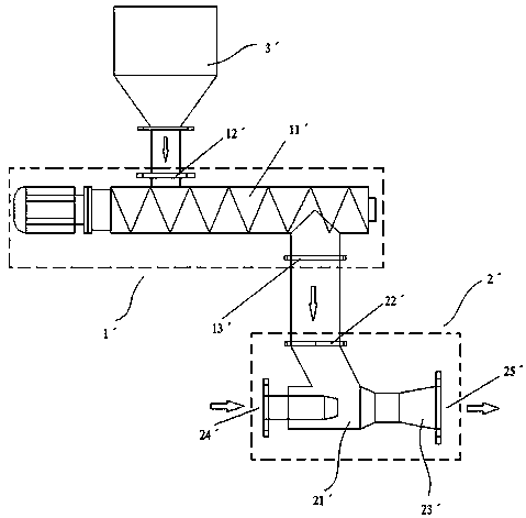
[0004] 1. The nozzle of the injector is far away from the throat, correspondingly, the blowing distance of the material is also long, requiring greater air supply power, high energy consumption, low injection efficiency, and easy to cause material return; for materials that are easy to stick to the wall, Due to the trumpet-type enlarged structure of the injector nozzle, the material is easy to stick to the nozzle wall, causing the throat to be blocked together, causing the material to be unable to be conveyed normally;
[0005] 2. There is no anti-bridging device at the feed port of the material, especially for powder materials with poor fluidity, it is easy to bridge and cause blockage, which makes the screw conveyor idling;
[0006] 3. Since it is assembled by soft connection of two independent devices, the metering screw conveying system and the air conveying system often have mismatching problems in performance and power consumption, resulting in high energy consumption and low work efficiency

Method used


Image

  • Air conveying type spiral feeding system
  • Air conveying type spiral feeding system

Examples


Embodiment

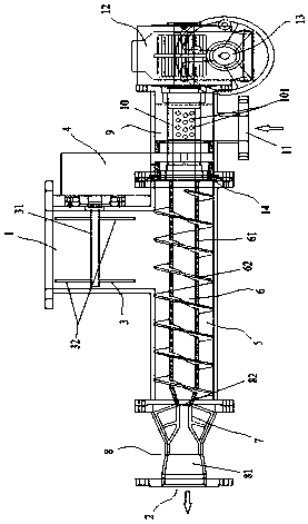
[0020] Such as figure 2 As shown, an air-driven screw feeding system includes a material inlet 1, a material outlet 2, an anti-bypass device 3, a transmission box 4, a mixing chamber 5, a screw conveyor 6, a reamer 7, an ejector 8, an air inlet Chamber 9, ventilation pipe 10, air inlet 11, reducer 12 and motor 13; one end of mixing chamber 5 is connected to injector 8, and the other end is connected to air inlet chamber 9, and the air inlet chamber 9 communicates with air inlet 11, and the injection The nozzle 81 of the device 8 communicates with the material outlet 2, the air inlet chamber 9, the mixing chamber 5 and the injector 8 are all sealed and separated, the upper end of the material inlet 1 is provided with an anti-bridging device 3, and the material inlet 1 is connected to the mixing chamber. 5, the mixing chamber 5 is provided with a screw conveyor 6, the screw conveyor 6 includes a spiral tube 61 and a spiral sheet 62 wound on the outer wall of the spiral tube 61,...


PUM


Abstract

An air conveying type spiral feeding system includes a material inlet, a material outlet, an anti-bridging device, a transmission case, a mixing chamber, a screw conveyor, reamers, an ejector, an inlet air chamber, a ventilation duct, an air inlet, a speed reducer and a motor. The inlet air chamber, the mixing chamber and the ejector are sealingly separated; the upper end of the material inlet isprovided with the anti-bridging device; the material inlet communicates with the mixing chamber; the screw conveyor is disposed inside the mixing chamber; the screw conveyor includes a hollow spiral pipe and spiral blades winding the outer wall of the spiral pipe; the reamers are disposed at a connecting position between a throat port of the ejector and the spiral pipe; the ventilation duct is disposed inside the air inlet chamber; the pipe wall of the ventilation duct is provided with circular holes; the spiral pipe is coaxially connected to the pipe port of the ventilation duct; the sealingjoint is surrounded with a gear; the gear engages with chain inside the transmission case to drive the anti-bridging device to rotate; and the ventilation duct is rotatably connected to an output shaft of the motor through the speed reducer. The invention provides an integrated air conveying type spiral feeding system having the characteristics of low power consumption, smooth batching operation and high efficiency.

Description

technical field [0001] The invention relates to the field of batching equipment for powder materials, in particular to an air-driven screw feeding system. Background technique [0002] At present, in the fields of building materials, metallurgy, electric power, chemical industry, etc., the batching process of powder materials is often involved, such as figure 1 Shown is a common batching device in the industry, where 1ˊ is the screw conveying system, 11ˊ is the screw conveyor, 12ˊ is the feeding port, 13ˊ is the feeding port, 2ˊ is the air delivery system, 21ˊ is the injector, 22ˊ is the Throat, 23ˊ is the nozzle, 24ˊ is the air inlet, 25ˊ is the outlet of the mixture, 3ˊ is the material bin, the screw conveying system and the air conveying system are two separate devices that are assembled and used after being softly connected. The work of this assembly device Principle: After the material enters from the material bin, it is fed to the screw conveyor through the feeding po...

Claims


Application Information

Patent Timeline
Patent Type & Authority Applications(China)
IPC IPC(8): B65G37/00
CPCB65G37/00
Inventor 张卫
Owner 上海洋野流体设备有限公司
Learn More