Connecting assembly

A technology for connecting components and components, applied in the direction of connecting components, non-mechanical drive clutches, fluid drive clutches, etc., can solve problems such as time-consuming work steps, and achieve the effect of saving assembly costs, saving additional materials, and reducing weight

Active Publication Date: 2018-10-09
SCHAEFFLER TECH AG & CO KG
View PDF8 Cites 0 Cited by
  • Summary
  • Abstract
  • Description
  • Claims
  • Application Information

AI Technical Summary

Problems solved by technology

The assembly of the bolts creates an additional time-consuming work step
In addition, additional components also create additional weight

Method used


Image

  • Connecting assembly
  • Connecting assembly
  • Connecting assembly

Examples


Embodiment Construction

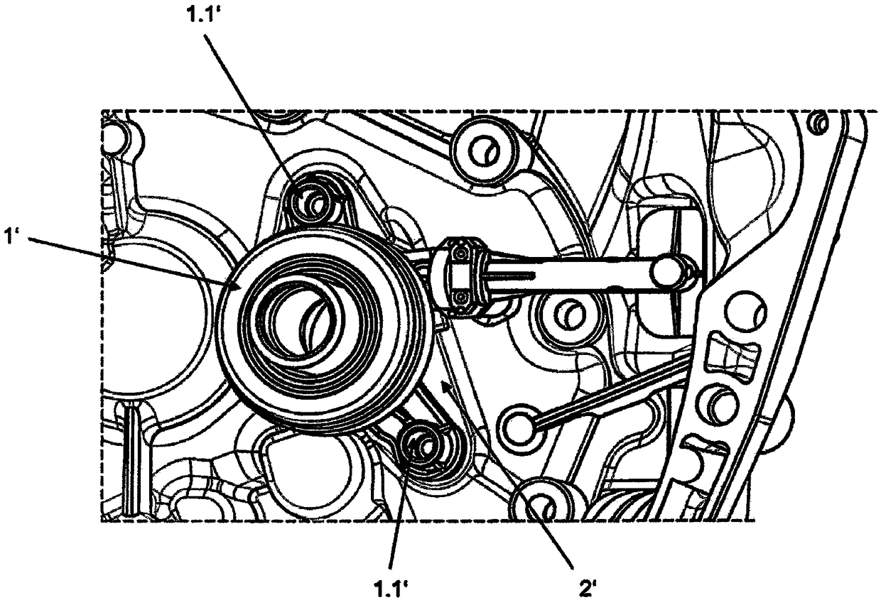
[0035] figure 1 The CSC is shown fixed to the clutch housing 2' in a typical variant according to the prior art. The CSC here has a cylinder housing 1' on which two webs 1.1' pointing radially outward are arranged. Screw the cylinder housing 1' onto the clutch housing 2' on the connecting plate 1.1'.

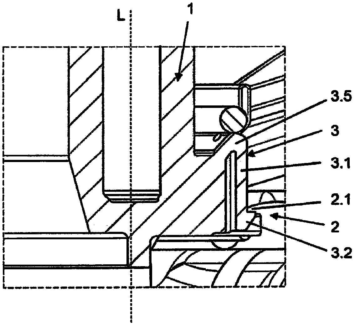
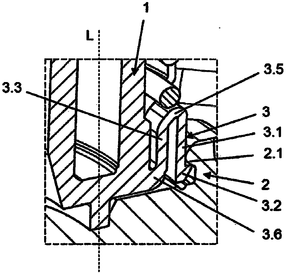
[0036] exist figure 2 A longitudinal section through a fastening element 3 according to the invention is shown in . In this case, the fastening element 3 is arranged radially outward on the cylinder housing 1 . The fastening element 3 has elastically configured flanks 3 . 1 extending parallel to the longitudinal axis L of the cylinder housing 1 , on whose free ends radially outwardly directed snap-in hooks 3 . 2 are arranged. The flanks 3.1 are connected to the cylinder housing 1 via a first connecting region 3.5. The flanks 3.1 can be compressed radially inwards during assembly and spring back into their initial position after assembly, in which they engage in correspondi...


PUM


Abstract

The invention provides a connecting assembly which is used for engaging a piston cylinder module, particularly a CSC with an engaging element (2), wherein the piston cylinder module has a cylinder housing (1); the piston is configured in a chamber of the cylinder housing (1) in a movable manner in an axial direction; and the cylinder housing (1) is fixed to the engaging element (2) in a releasablemanner. According to the connecting assembly, at least two fixing elements (3) are configured in the peripheral edge. The cylinder housing (1) can be fixed to the engaging element (2) through the fixing elements by means of a locking connecting device.

Description

technical field [0001] The invention relates to a connection assembly according to the preamble of the first claim for engaging a piston-cylinder module, in particular a CSC, on an adapter element. Background technique [0002] A hydraulic cylinder (part of the hydraulic circuit for actuating a clutch, such as a slave cylinder) essentially consists of a housing with an axially movable piston arranged therein, which is sealed so as to achieve Shell pressure transmission. [0003] If the slave cylinder is arranged concentrically with respect to the transmission input shaft, the piston arranged in the cylinder housing is designed as a ring piston for the penetration of the transmission input shaft. This type of slave cylinder is also known as a CSC or center splitter. In this case, an annular piston slides in an annular bore defined between the inner and outer cylinder walls of the cylinder housing in order to generate an annular actuating chamber (pressure chamber). The int...

Claims


Application Information

Patent Timeline
Patent Type & Authority Applications(China)
IPC IPC(8): F16D25/12F15B15/14F15B15/20F16B1/02
CPCF15B15/1428F16B1/02F16D25/12F16B21/086F16D25/083F16D2300/12
Inventor D·M·罗伊特P·瓦格纳
Owner SCHAEFFLER TECH AG & CO KG
Why Eureka
Try Eureka