
Cold water phase change machine and heat pump system

A cold water and phase change technology, applied in the energy field, can solve problems such as inability to achieve deicing, and achieve the effects of facilitating debugging and observation, improving heat exchange efficiency, and enhancing ice removal effect.

Inactive Publication Date: 2018-10-09
青岛瑞焓清洁能源供热研究院
View PDF7 Cites 2 Cited by
  • Summary
  • Abstract
  • Description
  • Claims
  • Application Information

AI Technical Summary

Problems solved by technology

The patented scraper moves in a pendulum motion, leaving a motion dead zone, which cannot achieve complete deicing

Method used


Image

  • Cold water phase change machine and heat pump system
  • Cold water phase change machine and heat pump system
  • Cold water phase change machine and heat pump system

Examples


specific Embodiment approach 1

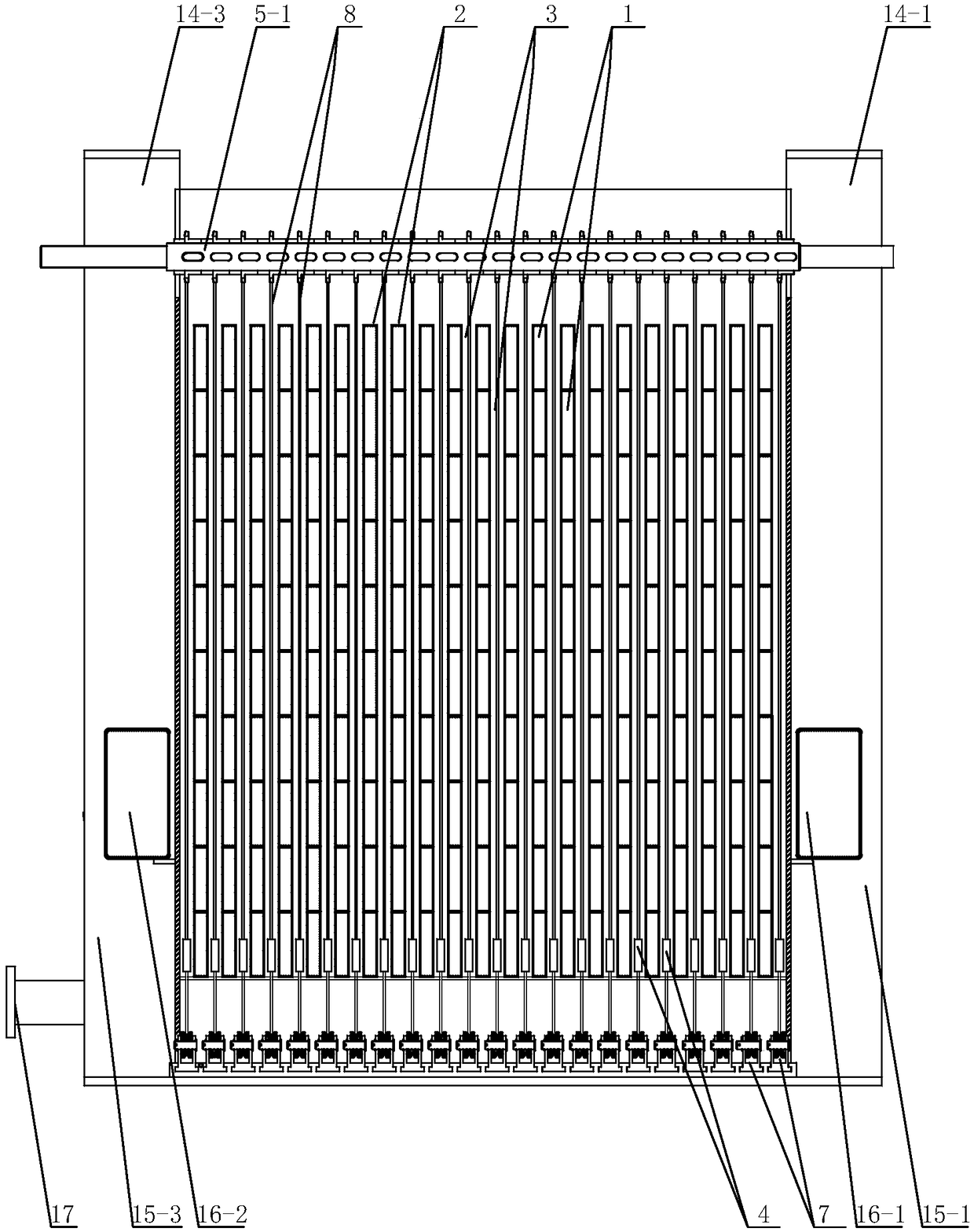
[0042] Specific implementation mode one, such as Figure 1~5 As shown, a cold water phase change machine of this embodiment is composed of a heat exchange tube 1, a tube row 2, a cold water flow channel 3, a scraper 4, a main shaft 5-1, a main shaft 2 5-2, an upper transmission wheel 6, a lower Transmission wheel 7, transmission chain 8, housing 9, left diversion box 10, right diversion box 11, antifreeze solution inlet 12, antifreeze solution outlet 13, ice discharge port one 14-1, ice discharge port two 14-2, Ice discharge port three 14-3, ice discharge port four 14-4, ice discharge channel one 15-1, ice discharge channel two 15-2, ice discharge channel three 15-3, ice discharge channel four 15-4, ice discharge channel Tube 1 16-1, ice discharge tube 2 16-2, cold water inlet 17, cold water inlet chamber 18 and cold water inlet 19, the plurality of heat exchange tubes 1 form a tube row 2 in the vertical direction, Both ends of a plurality of heat exchange tubes 1 are respect...

specific Embodiment approach 2

[0043] Specific implementation mode two, such as Image 6 As shown, a cold water phase change machine of this embodiment also includes a transmission motor one 20-1, a transmission motor two 20-2, a transmission motor reducer 21-1 and a transmission motor reducer two 21-2, so Described main shaft one 5-1 is connected with transmission motor reducer one 21-1; Described transmission motor reducer one 21-1 is connected with transmission motor one 20-1; Described main shaft two 5-2 and transmission The second motor reducer 21-2 is connected; the second transmission motor reducer 21-2 is connected to the second transmission motor 20-2. The beneficial effect of this embodiment is that the motor provides power for the main shaft.

specific Embodiment approach 3

[0044] Specific implementation mode three, such as Figure 7 As shown, a cold water phase change machine in this embodiment also includes a motor transmission chain 22, and the said main shaft two 5-2 is connected with the main shaft one 5-1 through the motor transmission chain 22. The beneficial effect of this embodiment is that the use of one motor is reduced through the transmission effect of the motor transmission chain.


PUM


Abstract

The invention discloses a cold water phase change machine and a heat pump system, and belongs to the technical field of energy sources. According to the cold water phase change machine and the heat pump system, phase change latent heat released when water is changed to ice is extracted from the cold water. The device comprises heat exchange pipes, pipe rows, cold water flow channels, a scraper, atransmission chain, main shafts, transmission wheels, a transmission motor, a transmission motor reducer, an ice breaking propeller, an external observable travel control device, a shell, a left flowguide box, a right flow guide box, an anti-freezing water solution inlet, an anti-freezing water solution outlet, a cold water inlet, ice discharging openings, a cold water inlet cavity and cold waterinlets. According to the cold water phase change machine and the heat pump system, an ice layer is scraped by the vertical reciprocating motion of the scraper, the ice layer is crushed and pushed tothe ice discharging openings, so that efficient ice removing and ice discharging of the cold water phase change machine are realized; and the machine and the system are suitable for heat pump heat supply and air conditioner ice cold accumulation systems capable of extracting the cold water phase change energy.

Description

technical field [0001] The invention relates to a cold water phase change machine and a heat pump system which release latent heat of phase change for external heating when cold water is extracted by heat pump technology and belongs to the field of energy technology. Background technique [0002] Using heat pump technology to extract the huge phase change latent heat contained in cold water for heating and cooling of buildings, that is, cold water phase change energy heat pump, is one of the effective ways to save energy and reduce emissions, and has huge energy saving, environmental protection and economic value. However, in the actual application of the cold water phase change energy heat pump system, because the existing technology cannot realize the uninterrupted cycle of heat extraction, freezing, deicing and re-icing, the heat pump system cannot continuously extract the phase change energy from the water, That is, the heat pump system cannot supply heat continuously. ...

Claims


Application Information

Patent Timeline
Patent Type & Authority Applications(China)
IPC IPC(8): F25C5/12F24D11/02
CPCF24D11/0214F25C5/12Y02B30/52
Inventor 吴荣华
Owner 青岛瑞焓清洁能源供热研究院
Learn More