
Dynamic vapor-liquid balance measuring device

A measuring device and method of steam technology, applied in the field of experimental equipment, can solve the problems of no heat preservation, air leakage, experimental errors, etc., and achieve the effects of avoiding overheating of the kettle liquid, controllable heat source temperature, and saving test time

Pending Publication Date: 2018-10-09
泰州学院
View PDF0 Cites 0 Cited by
  • Summary
  • Abstract
  • Description
  • Claims
  • Application Information

AI Technical Summary

Problems solved by technology

[0003] For the commonly used devices for teaching, there are mainly the following shortcomings: 1) The device has no thermometer casing, and the thermometer is inserted into the balance kettle, which needs to be sealed with a rubber plug, which is easy to corrode and deform, causing air leakage, polluting the environment, and causing experimental errors; 2) The device When the device is sampling in the vapor and liquid phases, it is necessary to remove the sealing plug and use a rubber dropper to sample, which will easily cause light components to volatilize, pollute the indoor environment, and cause experimental deviations; 3) The device uses resistance wire heating, which is not suitable for stable measurement The chemical compound system with poor resistance can easily lead to the decomposition of the compound. At the same time, the resistance wire is heated by an open flame, which has potential safety hazards; 4) It is difficult to achieve stable voltage control by using resistance wire heating, and it is prone to overheating or overcooling, resulting in balance deviation and experimental errors. ; 5) It is difficult for the device to measure the low-pressure vapor-liquid equilibrium; 6) It is difficult to grasp whether the vapor-liquid two phases are in equilibrium, and it is easy to cause deviation; 7) The device is not equipped with a vapor-liquid fluid separation component, When boiling violently, the liquid phase is easy to contaminate the vapor phase sample; 8) There is no heat preservation in the rising section of the vapor phase of the device, which may easily cause the rising steam to condense prematurely
[0004] However, the commonly used devices for scientific research have the following shortcomings: 1) The device is heated by resistance wire, which is not suitable for measuring the compound system with poor stability, and it is easy to cause the compound to decompose. At the same time, the resistance wire is heated by an open flame, which has potential safety hazards; Heating, it is difficult to achieve stable voltage control, prone to overheating or overcooling, resulting in balance deviation, resulting in experimental errors; 3) The temperature of the sample taken in the vapor and liquid phases of the device is relatively high, and the sampling process is easy to volatilize and cause errors; 4) The There is a dead angle in the liquid phase sampling port of the device, and it is not easy to replace during the circulation process, and the liquid phase fluid is easy to mix into the sample and be taken out at the moment of sampling imbalance; 5) The device is difficult to operate, prone to bumping, and easy to leak when measuring low-pressure vapor-liquid equilibrium , it is difficult to collect equilibrium gas and liquid two-phase samples at the same time, and there are serious deficiencies

Method used


Image

  • Dynamic vapor-liquid balance measuring device
  • Dynamic vapor-liquid balance measuring device
  • Dynamic vapor-liquid balance measuring device

Examples


Embodiment 1

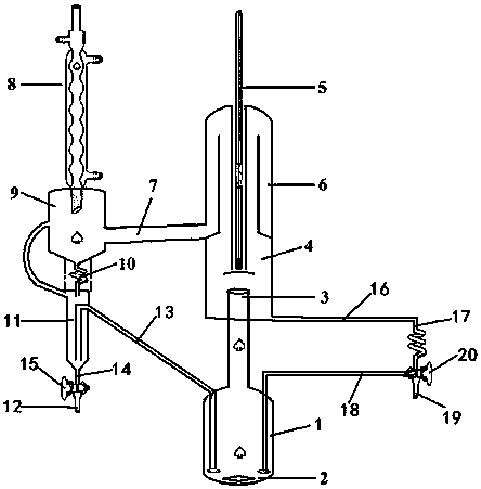
[0028] Such as figure 1 A dynamic vapor-liquid balance measuring device shown includes a balance kettle 1, a vapor-liquid separation bottle 4, a vapor phase condensing device, and several flow tubes.

[0029] The balance tank 1 is provided with a stirring magnet 2 , and the top of the balance tank 1 protrudes outward to form a gas-liquid mixing overflow port 3 . The vapor-liquid mixing overflow port 3 extends into the vapor-liquid separation bottle 4 from the bottom of the vapor-liquid separation bottle 4 . The bottom of the vapor-liquid separation bottle 4 is horizontal, and one side of the bottom is provided with a liquid phase outlet. One top end of the liquid phase flow pipe is connected with the liquid phase outlet, and the other end extends into the equilibrium tank 1 and communicates with the inside of the equilibrium tank 1 . The middle of the vapor-liquid separation bottle 4 is recessed from the top to form a groove, that is, the cross-section of the vapor-liquid se...

Embodiment 2

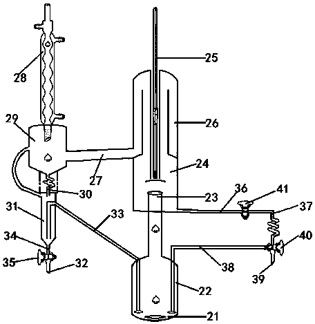
[0036] Such as figure 2 A dynamic vapor-liquid balance measuring device shown includes a balance kettle 21, a vapor-liquid separation bottle 24, a vapor phase condensing device, and several flow tubes.

[0037] A stirring magnet 22 is installed inside the balance tank 21 , and the top of the balance tank 21 protrudes outward to form a vapor-liquid mixing overflow port 23 . The vapor-liquid mixing overflow port 23 extends into the vapor-liquid separation bottle 24 from the bottom of the vapor-liquid separation bottle 24 . The bottom of the vapor-liquid separation bottle 24 is horizontal, and one side of the bottom is provided with a liquid phase outlet. One top end of the liquid phase flow pipe is connected to the liquid phase outlet, and the other top end extends into the balance tank 21 and communicates with the balance tank 21 . The middle part of the vapor-liquid separation bottle 24 is recessed from the top to form a groove, that is, the cross-section of the vapor-liqui...

Embodiment 3

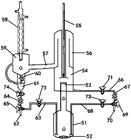
[0045] Such as image 3 A dynamic vapor-liquid balance measuring device shown includes a balance kettle 51, a vapor-liquid separation bottle 54, a vapor phase condensing device, and several flow tubes.

[0046] A stirring magnet 52 is installed inside the balance tank 51 , and the top of the balance tank 51 protrudes outward to form a vapor-liquid mixing overflow port 53 . The vapor-liquid mixing overflow port 53 extends into the vapor-liquid separation bottle 54 from the bottom of the vapor-liquid separation bottle 54 . The bottom of the vapor-liquid separation bottle 54 is horizontal, and one side of the bottom is provided with a liquid phase outlet. One top end of the liquid phase flow pipe is connected with the liquid phase outlet, and the other end extends into the equilibrium tank 51 and communicates with the inside of the equilibrium tank 51 . The middle part of the vapor-liquid separation bottle 54 is recessed from the top to form a groove, that is, the cross-section...


PUM


Abstract

The invention provides a dynamic vapor-liquid balance measuring device, which comprises an equilibrium still, a vapor-liquid separation bottle, a vapor phase condensing device and a plurality of flowtubes, wherein a stirring magneton is disposed in the equilibrium still; a liquid phase outlet is arranged at one side of the horizontal bottom of the vapor-liquid separation bottle; the top end of the first liquid phase flow tube is connected to the liquid phase outlet with an included angle of 0.5 to 10 degrees; a liquid phase sampling opening is formed in the top end of the second liquid phaseflow tube, and the portion, close to the liquid phase sampling opening, of the second liquid phase flow tube is communicated with the interior of the top end of the third liquid phase flow tube through a third liquid phase reflux shutoff valve. The dynamic vapor-liquid balance measuring device is additionally provided with the stirring magneton, and the stirring magneton is driven to rotate by oilbath heating, so as to avoid liquid flooding. The first liquid phase flow tube and the vapor-liquid separation bottle are designed to eliminate a liquid phase dead angle in an existing device. The spiral return tube is designed to eliminate the problem of volatilization loss caused by the too high temperature of liquid phase and vapor phase samples in the using process of existing device.

Description

technical field [0001] The invention belongs to the field of experimental equipment, in particular to a vapor-liquid balance measuring device. Background technique [0002] There are basically two kinds of devices for the determination of the vapor-liquid equilibrium dynamic method of miscible systems, one is commonly used for teaching, and the other is commonly used for scientific research. Through the long-term use of the above two devices for measurement work, it is found that both have their own advantages and disadvantages. [0003] For the commonly used devices for teaching, there are mainly the following shortcomings: 1) The device has no thermometer casing, and the thermometer is inserted into the balance kettle, which needs to be sealed with a rubber plug, which is easy to corrode and deform, causing air leakage, polluting the environment, and causing experimental errors; 2) The device When the device is sampling in the vapor and liquid phases, it is necessary to r...

Claims


Application Information

Patent Timeline
Patent Type & Authority Applications(China)
IPC IPC(8): G01N25/12
CPCG01N25/12
Inventor 宋玉鹤宋娟胡志强梁吉雷韦平和王洁邓加竹
Owner 泰州学院
Learn More