Circuit and method for measuring operational amplification bias current and shielding control unit

A technology of control unit and bias current, applied in the field of electronics, can solve the problem of inability to realize accurate current measurement of operational amplifiers, inability to measure bias current of FET input operational amplifiers, and test accuracy that cannot reach nanoampere and picoampere precision, etc. problem, to achieve the effect of not easy self-excitation phenomenon, effective measurement, and strong stability

Pending Publication Date: 2018-10-09
北京励芯泰思特测试技术有限公司
View PDF0 Cites 2 Cited by
  • Summary
  • Abstract
  • Description
  • Claims
  • Application Information

AI Technical Summary

Problems solved by technology

[0003] The existing operational amplifier test equipment basically only has the test capability of ten nanoamperes, and one of the important characteristics of FET input operational amplifiers is that the input bias current can be between several nanoamperes and several picoamperes. , the existing test equipment with only ten nanoampere test capabilities cannot accurately and effectively measure the bias current of FET input operational ampli

Method used


Image

  • Circuit and method for measuring operational amplification bias current and shielding control unit
  • Circuit and method for measuring operational amplification bias current and shielding control unit
  • Circuit and method for measuring operational amplification bias current and shielding control unit

Examples


Embodiment Construction

[0093] Exemplary embodiments of the present disclosure will be described in more detail below with reference to the accompanying drawings. Although exemplary embodiments of the present disclosure are shown in the drawings, it should be understood that the present disclosure may be embodied in various forms and should not be limited by the embodiments set forth herein. Rather, these embodiments are provided for more thorough understanding of the present disclosure and to fully convey the scope of the present disclosure to those skilled in the art.

[0094] In order to illustrate the technical solutions of the present invention, specific examples are used below to illustrate.

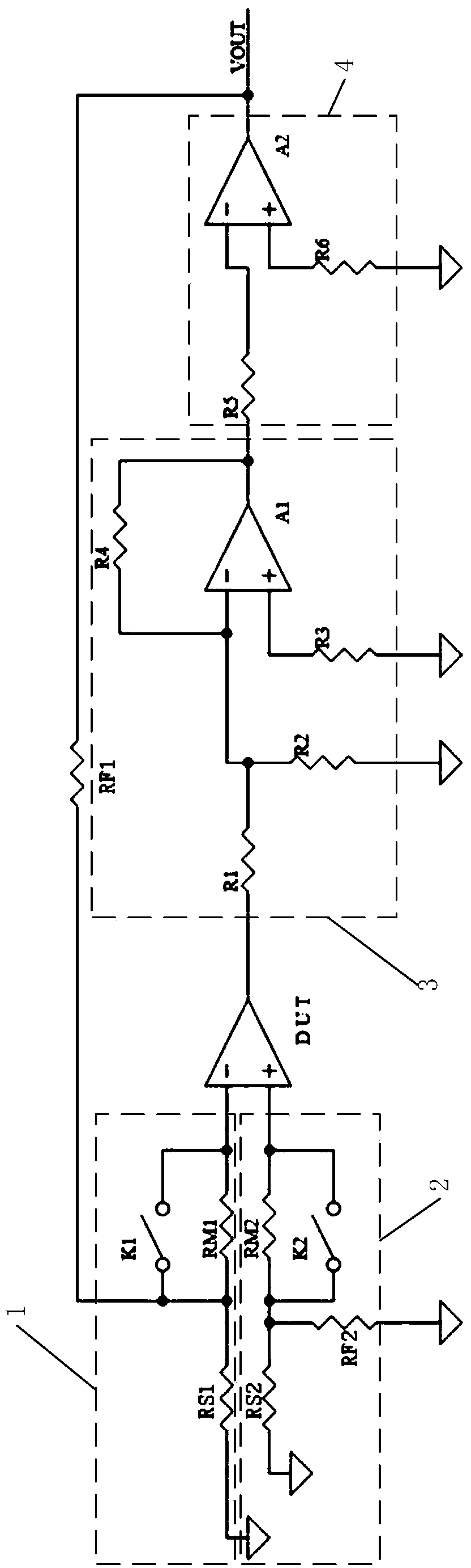
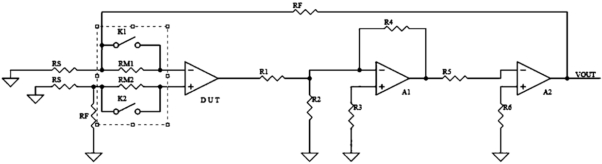
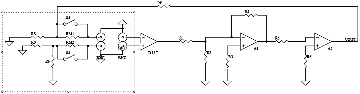
[0095] In the first aspect, an embodiment of the present invention provides a circuit for measuring the bias current of an operational amplifier, such as figure 1 shown, including:

[0096] The inverting input terminal control unit 1 is connected to the inverting input terminal of the operational amplif...


PUM


Abstract

The invention discloses a circuit and method for measuring operational amplification bias current and a shielding control unit. The circuit includes an inverted input terminal control unit connected with an inverted input terminal of a to-be-tested operational amplifier; an in-phase input terminal control unit connected with an in-phase input terminal of the to-be-tested operational amplifier; a first auxiliary operation amplification unit whose inverted input terminal is connected with the output terminal of the to-be-tested operational amplifier and whose in-phase input terminal is in grounded connection; a second auxiliary operation amplification unit whose inverted input terminal is connected with the output terminal of the first auxiliary operation amplification unit and whose in-phase input terminal is in grounded connection and whose output terminal outputs electrical signals; a feedback resistor connected between the inverted-phase input terminal of the to-be-tested operationalamplifier and the output terminal of the second auxiliary operational amplification unit so as to form a negative feedback circuit. The invention solves problems of low precision and poor stability in measurement of input bias current of operational amplification device in the prior art; the measurement precision is accurate to picoamp level from nanoamp level and market demands are met.

Description

technical field [0001] The invention relates to the field of electronic technology, in particular to a circuit and method for measuring the bias current of an operational amplifier and a shielding control unit. Background technique [0002] With the continuous improvement of the semiconductor manufacturing process, the production cost is gradually reduced, and the field effect transistor input operational amplifier (hereinafter referred to as the FET input operational amplifier) ​​is gradually popularizing in various fields. When the operational amplifier is applied, it is necessary to measure the parameters of the operational amplifier, such as the bias current and other parameters, to ensure the normal performance of the operational amplifier. [0003] The existing operational amplifier test equipment basically only has the test capability of ten nanoamperes, and one of the important characteristics of FET input operational amplifiers is that the input bias current can be ...

Claims


Application Information

Patent Timeline
IPC IPC(8): G01R19/00
CPCG01R19/00
Inventor 李力军乔晖
Owner 北京励芯泰思特测试技术有限公司
Why Eureka
Try Eureka