A reference signal mapping method, network device, and terminal device
A mapping method and technology for terminal equipment, applied in the field of communication, can solve problems such as overhead, impact port, and layer number indication overhead, etc.
- Summary
- Abstract
- Description
- Claims
- Application Information
AI Technical Summary
Problems solved by technology
Method used
Image
Examples
Embodiment 1
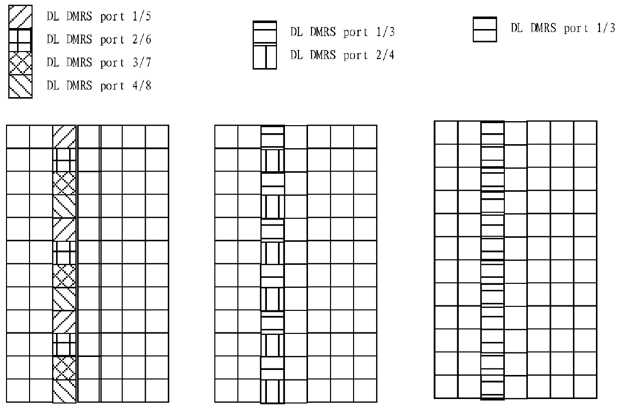
[0187] In Embodiment 1 of the present application, based on the DL and UL DMRS design principles already determined in the NR standard, combined with the DL DMRS design of each clock, the DL and UL DMRS port mapping is reasonably designed to avoid unnecessary indication overhead. The NR standard determines that DL DMRS port multiplexing adopts FDM (including comb), CDM (including OCC and cyclic shift) and TDM. According to several main DL DMRS designs at present, it can be seen that when the number of DL DMRS ports is small, FDM is mainly used for multiplexing.
[0188] Since the NR standard has agreed to adopt the common structure of uplink and downlink DMRS for CP-OFDM, it is considered that when designing the port mapping method of uplink DMRS and the indication method of port and space layer (layer), the port mapping of downlink DMRS and the port mapping of downlink DMRS will be used for reference. Indication method of port and space layer. If the uplink DMRS and downlink...
Embodiment 2
[0229] The main design principle of this embodiment is still to make at least one port in all port configurations corresponding to n in the downlink DMRS space layer number and at least one port in all port configurations corresponding to m in the uplink DMRS space layer number The resources corresponding to the configuration are different. However, in this embodiment, it is assumed that the port mapping of the uplink and downlink DMRS uses a similar rule, that is, some or all port numbers of the uplink DMRS and downlink DMRS are mapped to the same frequency domain position from low to high. In this case, by designing the uplink and downlink DMRS ports and the indication content of the number of space layers, it is also possible to realize that the configuration of at least one port with a number of space layers n is different from the configuration corresponding to at least one port configuration with an uplink number of space layers m. , that is, the configuration of the upl...
Embodiment 3
[0256] In Embodiments 1 and 2, it is assumed that the uplink and downlink DMRS are orthogonal using the FDM method. In this embodiment, it is considered that the uplink and downlink DMRS are orthogonal using the CDM (including OCC or cyclic shift) method. It is assumed that the DL DMRS is multiplexed using the following method, that is, port x0-x3 is multiplexed using the FDM method, and port x4-x7 and port x0-x3 are multiplexed on the same RE using the CDM method. A similar multiplexing method is also used in the uplink, that is, port y0-y3 is multiplexed using the FDM method, and port y4-y7 and port y0-y3 are multiplexed using the CDM method on the same RE, such as Figure 15 shown.
[0257] Assuming that the CDM is frequency-domain or time-domain OCC (the method shown in the schematic diagram is the frequency-domain OCC method, and this embodiment is also applicable to the time-domain OCC method), the multiplexing of two ports only requires OCC with a length of 2, respecti...
PUM
 Abstract
Description
Claims
Application Information
 - R&D
- Intellectual Property
- Life Sciences
- Materials
- Tech Scout
- Unparalleled Data Quality
- Higher Quality Content
- 60% Fewer Hallucinations
Browse by: Latest US Patents, China's latest patents, Technical Efficacy Thesaurus, Application Domain, Technology Topic, Popular Technical Reports.
© 2025 PatSnap. All rights reserved.Legal|Privacy policy|Modern Slavery Act Transparency Statement|Sitemap|About US| Contact US: help@patsnap.com


