Correcting device for rectangular plate splicing

A correction device and a rectangular plate technology, applied in the field of sheet metal welding, can solve the problems of low efficiency, time-consuming and labor-intensive, and low welding seam adjustment accuracy.

Inactive Publication Date: 2018-10-12
WUHU JUNRU THERMAL INSULATION MATERIAL CO LTD
View PDF7 Cites 13 Cited by
  • Summary
  • Abstract
  • Description
  • Claims
  • Application Information

AI Technical Summary

Problems solved by technology

[0002] The raw material of the water tank is stainless steel plate, which is rolled and welded into the cylinder of the water tank, and the circular cover and the bottom of the water tank are cut from the plate, and welded to both ends of the cylinder to obtain a circular water tank. The plate in the factory The width of the roll is fixed. For the water tank whose height is greater than the width of the coil, it is necessary to splice multiple plates and then roll them into a cylinder. Set up transport rollers at both ends of the splicing machine, and separate the two spliced ​​plates from the two ends. The transport roller is pushed to the joint of the jigsaw machine, and the worker uses the pry bar to adjust the position of the two plates, so that the two ends of the two plates are aligned and kept parallel to each other without inclination, so as to ensure that the welds between the plates are of the same size. Manual operation is time-consuming and labor-intensive, with low efficiency and low accuracy of weld adjustment

Method used


Image

  • Correcting device for rectangular plate splicing
  • Correcting device for rectangular plate splicing
  • Correcting device for rectangular plate splicing

Examples


specific Embodiment approach

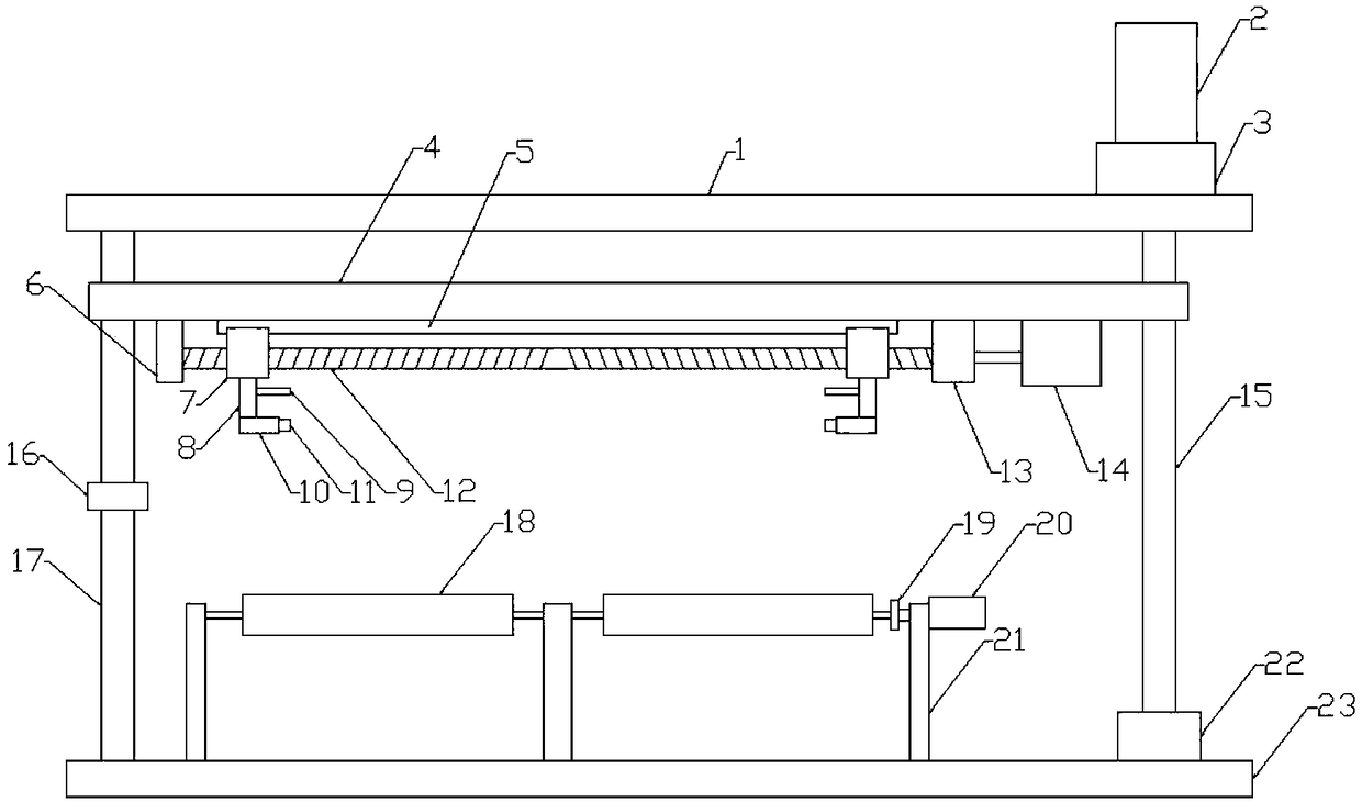
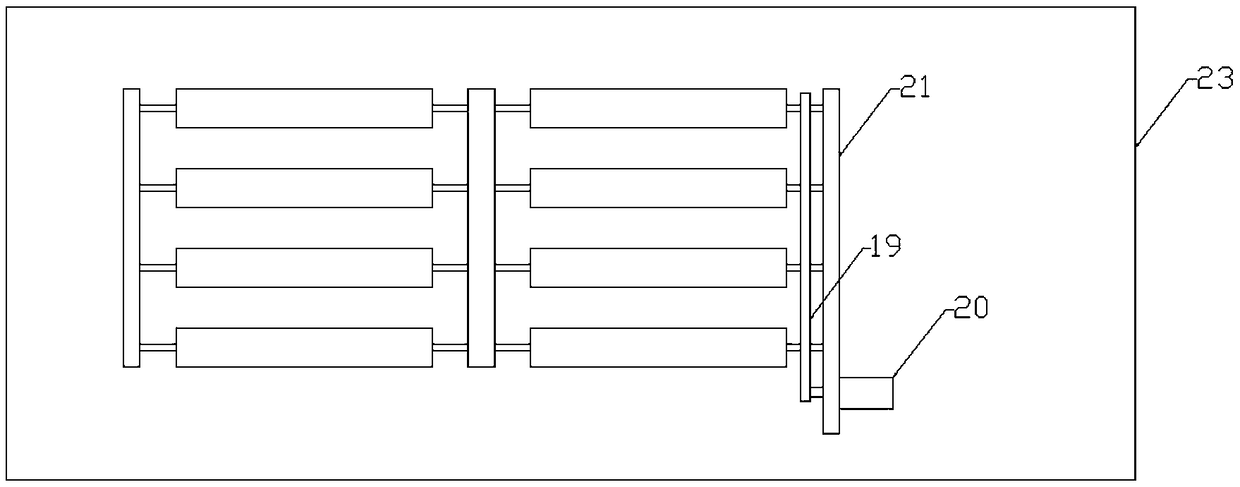
[0014] Figure 1-3 A specific embodiment of the present invention is shown: a correction device for splicing rectangular plates, including a top plate 1 and a bottom plate 23, a support 21 is provided in the middle of the bottom plate 23, and a plurality of rollers 18 are uniformly arranged on the support 21, so that A transmission motor 20 is fixed on the side of the support 21, the transmission motor 20 is connected with the roller 18 through a transmission belt 19, a slide bar 17 is fixed at one end of the bottom plate 23, and the other end of the slide bar 17 is fixed on the top plate 1, the Bottom plate 23 other ends are fixed with screw mandrel supporting seat-22, and described top plate 1 upper end is provided with motor driving seat-3, and described motor driving seat-3 and screw mandrel supporting seat-22 are provided with screw mandrel 15, and described motor driving seat-3 and screw mandrel supporting seat-22 are provided with screw mandrel 15, and The stepping moto...


PUM


Abstract

The invention discloses a correcting device for rectangular plate splicing. The correcting device comprises a top plate and a bottom plate. A support is arranged at the middle portion of the bottom plate and provided with a plurality of rollers. A transmission motor is fixed to the side face of the support. A sliding rod is fixed to one end of the bottom plate, and a first lead screw supporting base is fixed to the other end of the bottom plate. A first motor transmission base is arranged at the upper end of the top plate. A lead screw is arranged in the first motor transmission base and the first lead screw supporting base. A stepping motor is fixed to the upper end of the first motor transmission base. The lead screw is provided with a sliding plate. A sliding rail is arranged at the lower end of the sliding plate. A second lead screw supporting base and a second motor transmission base are arranged at the two ends of the sliding rail. A both-way lead screw is arranged between the second lead screw supporting base and the second motor transmission base. The lower end of the sliding plate is further provided with a servo motor. The both-way lead screw is provided with symmetric sliding bases. The lower ends of the sliding bases are provided with connecting plates. A plurality of connecting rods are evenly distributed at the lower ends of the connecting plates. Wheels are arranged at the front ends of the connecting rods. According to the correcting device, the trouble of manual plate adjustment is saved, the operation process is simple and fast, plate position adjustment is accurate, and the plate butt joint efficiency is improved.

Description

technical field [0001] The invention relates to the field of plate welding, in particular to a correction device for splicing rectangular plates. Background technique [0002] The raw material of the water tank is stainless steel plate, which is rolled and welded into the cylinder of the water tank, and the circular cover and the bottom of the water tank are cut on the plate, and welded to both ends of the cylinder to obtain a circular water tank. The plate in the factory The width of the roll is fixed. For the water tank whose height is greater than the width of the coil, it is necessary to splice multiple plates and then roll them into a cylinder. Set up transport rollers at both ends of the splicing machine, and separate the two spliced ​​plates from the two ends. The transport roller is pushed to the joint of the jigsaw machine, and the workers use the pry bar to adjust the position of the two plates so that the two ends of the two plates are aligned and kept parallel to...

Claims


Application Information

Patent Timeline
Patent Type & Authority Applications(China)
IPC IPC(8): B23K37/04
Inventor 艾莉
Owner WUHU JUNRU THERMAL INSULATION MATERIAL CO LTD
Why Eureka
Try Eureka