Mold splitting material taking device for optical mold
What is Al technical title?
Al technical title is built by PatSnap Al team. It summarizes the technical point description of the patent document.
A technology of reclaiming device and mould, applied in the direction of manufacturing tools, instruments, manipulators, etc., can solve the problems of inaccurate positioning of optical finished products, single movement trajectory, damage of optical finished products, etc., and achieves rapid action, flexible change, and short response time. Effect
Inactive Publication Date: 2018-10-12
GUANGDONG GMA OPTOELECTRONICS TECH +2
View PDF8 Cites 4 Cited by
Summary
Abstract
Description
Claims
Application Information
AI Technical Summary
This helps you quickly interpret patents by identifying the three key elements:
Problems solved by technology
Method used
Benefits of technology
Problems solved by technology
[0002] Existing optical mold splitting and retrieving devices are generally simple mechanical mechanisms or simple three-axis mechanical mechanisms. The movement trajectory is very single during the retrieving movement, and the positioning of the optical finished product is not precise enough, and it is easy to damage the optical finished product. Cause damage, and the failure rate is still high, it is inconvenient to replace
Method used
Image
Click on the blue label to locate the original text in one second.
Reading with bidirectional positioning of images and text.
Examples
Embodiment Construction
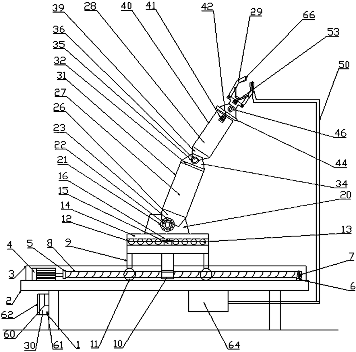
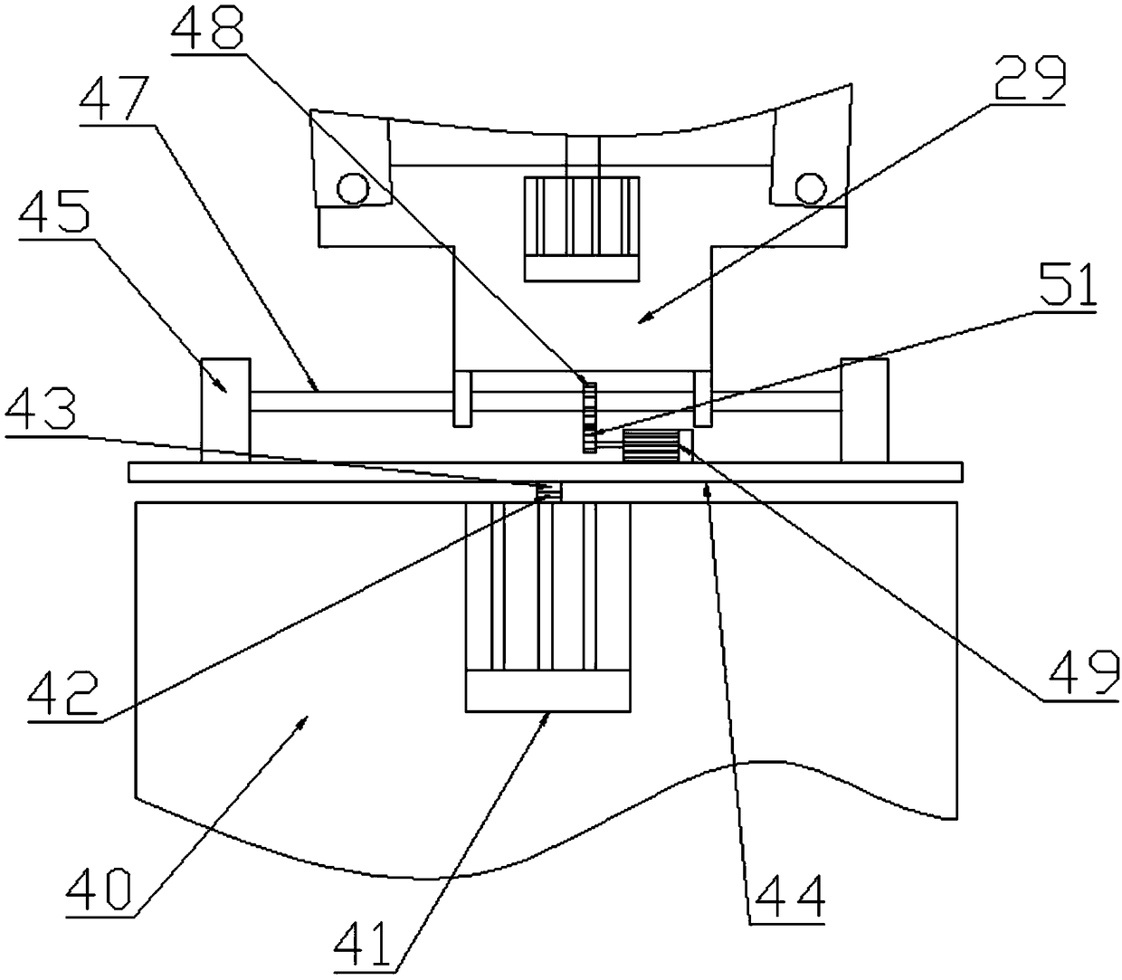
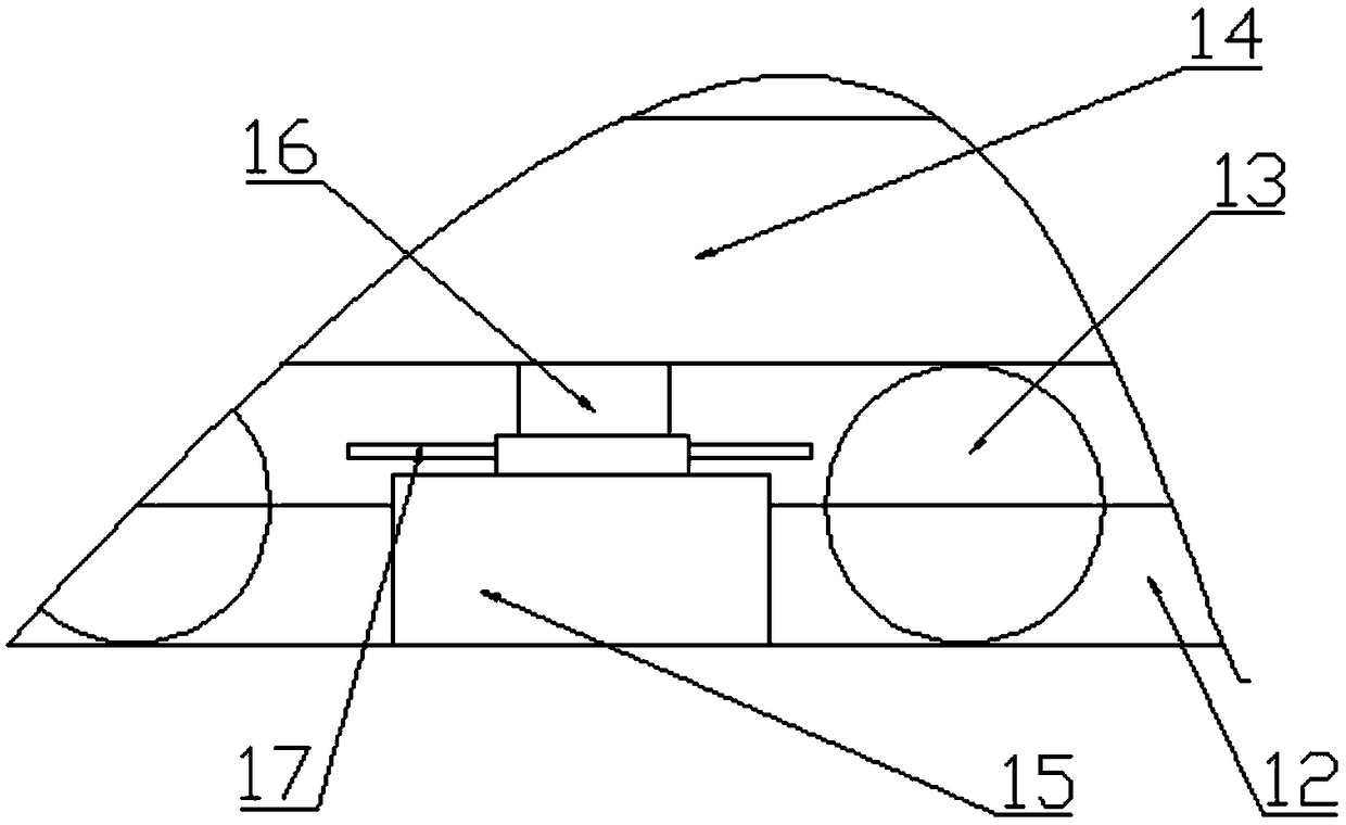
[0023] The present invention is specifically described below in conjunction with accompanying drawing, as Figure 1-7As shown, an optical mold splitting and taking-out device includes a bracket-1, and the bracket-1 is fixedly installed on the ground. The bracket-1 is provided with a base moving mechanism, and the base moving mechanism is fixedly installed on the bracket - Loading plate 2 on 1, two linear guide rails fixedly installed on the upper surface of the bearing plate 2 3, a stepping motor fixedly installed on one end of the upper surface of the bearing plate 2 and located in the middle of the two linear guide rails 3 - 4, fixed installation Coupling-5 at the output end of stepping motor-4, fixedly installed on the bearing plate 2 and screw seat 6 opposite to stepping motor-4, screw bearing 7 fixedly installed on the screw seat 6, one end The screw 8 fixedly installed on the coupling 5 and the other end fixedly installed on the screw bearing 7, the screw mounting seat 9...
PUM
Abstract
The invention discloses a mold splitting material taking device for an optical mold. The mold splitting material taking device comprises a support I, wherein a base moving mechanism is arranged on thesupport I and is provided with a bearing plate, two linear guide rails, a stepper motor I, a shaft coupling I, a lead screw seat, a lead screw bearing, a lead screw, a lead screw installing seat, a lead screw nut and a pulley; a turning and material taking mechanism is arranged on the base moving mechanism and is provided with an annular guide rail, a ball chain, a rotating seat, a rolling bearing pedestal, a stepped shaft, a gear I, a stepper motor II, a worm gear, a supporting seat I, a perforated circular hole I, a rotary shaft I, a gear II, a stepper motor III, a gear III, a supporting seat II, a large arm, a small arm and a clamping hand; a gas conveying mechanism is arranged at the bottom of the support I; and a controller is arranged at one side of the support I. The mold splittingmaterial taking device for the optical mold has the beneficial effects that the mold splitting material taking device is simple in structure and has high practicability.
Description
technical field [0001] The invention relates to the field of mechanical equipment, in particular to an optical mold splitting and taking-out device. Background technique [0002] Existing optical mold splitting and retrieving devices are generally simple mechanical mechanisms or simple three-axis mechanical mechanisms. The movement trajectory is very single during the retrieving movement, and the positioning of the optical finished product is not precise enough, and it is easy to damage the optical finished product. Cause damage, and the failure rate is still high, and it is inconvenient to replace. Contents of the invention [0003] The object of the present invention is to solve the above-mentioned problems, and a device for splitting and taking out optical molds is designed. [0004] To achieve the above object, the technical solution of the present invention is an optical mold splitting and taking-out device, comprising a bracket one, the bracket one is fixedly instal...
Claims
Application Information
Patent Timeline
Application Date:The date an application was filed.
Publication Date:The date a patent or application was officially published.
First Publication Date:The earliest publication date of a patent with the same application number.
Issue Date:Publication date of the patent grant document.
PCT Entry Date:The Entry date of PCT National Phase.
Estimated Expiry Date:The statutory expiry date of a patent right according to the Patent Law, and it is the longest term of protection that the patent right can achieve without the termination of the patent right due to other reasons(Term extension factor has been taken into account ).
Invalid Date:Actual expiry date is based on effective date or publication date of legal transaction data of invalid patent.