Forming method for precast concrete member bonding surface

A technology of prefabricated concrete and molding methods, which is applied in the direction of ceramic molding machines, manufacturing tools, mold auxiliary parts, etc., can solve the problems of complex process, insufficient roughness of joint surface forming process, high cost, etc., and achieve convenient and fast use, low price, Variety of effects

Inactive Publication Date: 2018-10-12
NANJING UNIV OF TECH
View PDF1 Cites 2 Cited by
  • Summary
  • Abstract
  • Description
  • Claims
  • Application Information

AI Technical Summary

Problems solved by technology

[0003] The purpose of the present invention is to provide a method for forming the joint surface of prefabricated concrete components, which can effectively solve the problems of insufficient roughness, complicated process and high cost of the existing joint surface forming process

Method used


Image

  • Forming method for precast concrete member bonding surface

Examples


Embodiment 1

[0016] In this embodiment, taking high roughness requirements as an example, the forming method of the joint surface of precast concrete components includes the following steps:

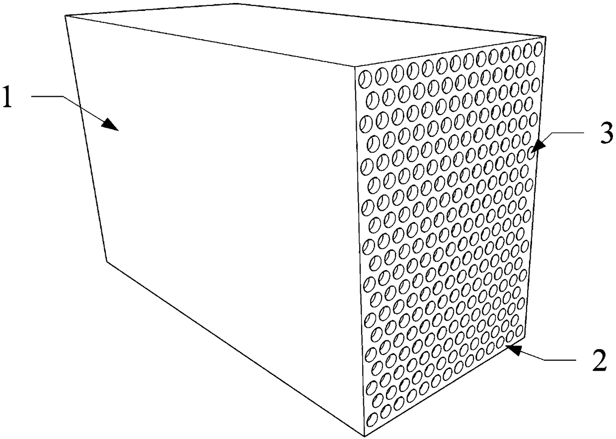
[0017] 1) Precast concrete component 1, taking precast concrete shear wall as an example;

[0018] 2) Paste the bubble film, wherein the bubble size of the bubble film is: 1cm in diameter, 0.6cm in height, and 1.3cm in spacing, and install the above bubble film in the template corresponding to the joint surface 2 of the precast concrete component 1 The surface, wherein the joint surface 2 is the surface where the precast concrete member 1 needs to be combined with the cast-in-situ concrete or the sitting grout layer, can be located at the bottom or side of the precast concrete shear wall and the end face of the precast concrete column or precast concrete beam; during specific implementation, Fix the bubble film on the template by gluing;

[0019] 3) Peel off the bubble film. After the template is re...

Embodiment 2

[0022] In this embodiment, taking low roughness as an example, the forming method of the joint surface of precast concrete components includes the following steps:

[0023] 1) Precast concrete component 1, taking precast concrete beams as an example;

[0024] 2) Paste the bubble film, wherein the bubble size of the bubble film is: 0.5cm in diameter, 0.3cm in height, and 1.3cm in spacing, and install the above bubble film on the template corresponding to the joint surface 2 of the precast concrete component 1 The inner surface, where the joint surface 2 is the surface where the precast concrete member 1 needs to be combined with the cast-in-situ concrete or the sitting grout layer, can be located on the bottom or side of the precast concrete shear wall and the end surface of the precast concrete column or precast concrete beam; , fix the bubble film on the template with thumbtacks;

[0025] 3) Peel off the bubble film. After the template is removed, peel off the bubble film. A...


PUM


Abstract

The invention relates to a forming method for a precast concrete member bonding surface. The method comprises the following steps that a concrete member is precast; an air bubble film is attached, specifically, the air bubble film is mounted on the inner surface, corresponding to the bonding surface of the precast concrete member, of a template; and the air bubble film is peeled off, specifically,after the template is dismounted, the air bubble film is peeled off, and concave pits which are consistent with the air bubble film in size and arrangement rule are formed in the precast concrete member bonding surface. According to the technical scheme, through the forming method for the precast concrete member bonding surface, the roughness requirement for the precast concrete member bonding surface is met through the air bubble film, the construction process is simple and convenient, the surface quality is good, in addition, materials of the air bubble film are easy to take, the price is low, and the advantages of customization and easy demolding are achieved.

Description

technical field [0001] The invention relates to the technical field of prefabricated concrete structures, in particular to a method for forming a joint surface of a prefabricated concrete component. Background technique [0002] There are a large number of cast-in-place concrete or sitting grout layers in the assembled monolithic concrete structure that follows the concept of "equivalent to cast-in-place", and the joint surface between precast concrete components and cast-in-place concrete or sit-in-place layers becomes the weak link of the structure. The bonding performance between new and old concrete or concrete and slurry is the key to determine the mechanical properties of the bonding surface. In order to improve the bonding performance of the material at the joint surface, the construction process of setting a rough surface at the joint surface is widely used. At present, the methods for setting the rough surface on the joint surface of precast concrete components inc...

Claims


Application Information

Patent Timeline
Patent Type & Authority Applications(China)
IPC IPC(8): B28B7/00
CPCB28B7/0002B28B7/0064
Inventor 朱张峰臧旭磊
Owner NANJING UNIV OF TECH
Why Eureka
Try Eureka