
In-mould hot-cutting automatic sprue cutting mould structure

An eager and automatic technology, applied in the field of molds, can solve the problems of product appearance quality, high labor intensity, and increased product scrap rate, and achieve the effect of improving product appearance quality, facilitating production automation, and ensuring quality consistency

Pending Publication Date: 2018-10-12
上海宝鹿车业有限公司
View PDF0 Cites 6 Cited by
  • Summary
  • Abstract
  • Description
  • Claims
  • Application Information

AI Technical Summary

Problems solved by technology

Under the existing technology, to achieve the purpose of automatic mold production, there are three ways: latent gate, point gate and hot runner directly pointing on the product, but many products cannot use these three gates due to structure and appearance requirements way, so as not to meet the requirements of automatic production, only the way of side gate glue injection can be used
The product and the runner cannot be separated when the side gate is glued into the mold and ejected. The runner and the product are connected through the gate. Secondary processing is required to separate the product from the runner. Workers need to trim the gate, which is labor-intensive. In this way, the efficiency will be greatly reduced, and there will be residual or lack of glue at the separation between the product and the runner during the secondary processing, the gate will not be trimmed beautifully, the appearance quality of the product will be affected, and the product scrap rate will also increase.

Method used


Image

  • In-mould hot-cutting automatic sprue cutting mould structure
  • In-mould hot-cutting automatic sprue cutting mould structure
  • In-mould hot-cutting automatic sprue cutting mould structure

Examples


Embodiment

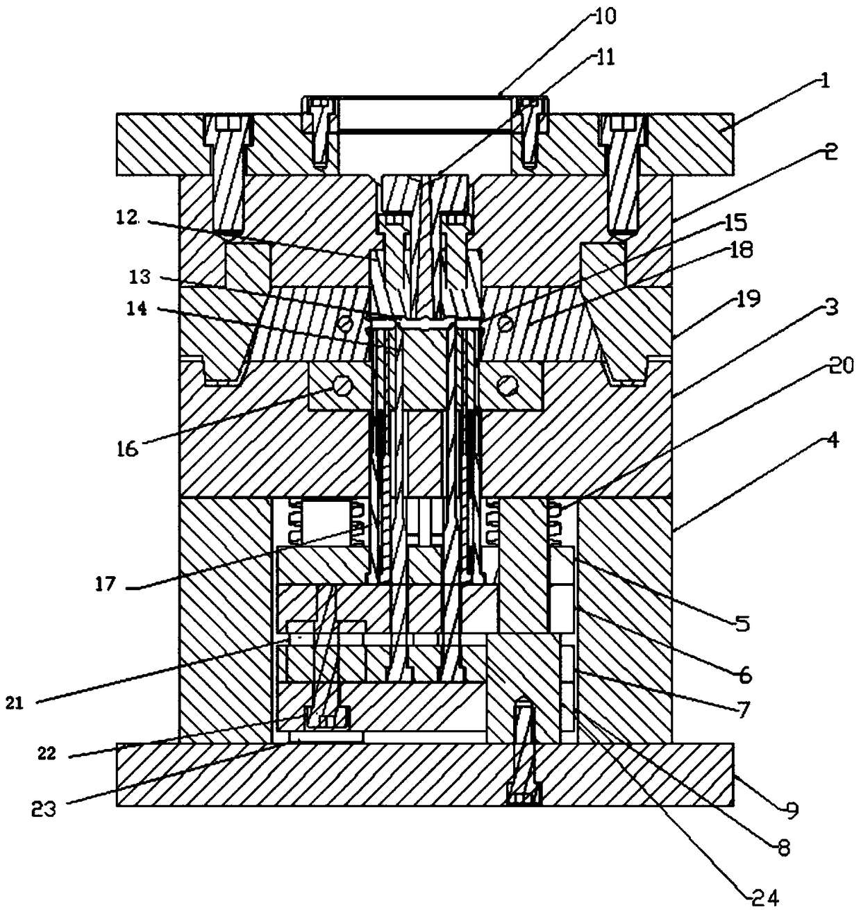
[0030] like figure 1 As shown, the injection molding machine closes the mold, and the front mold and the back mold are combined together. Injection molding machine starts to inject, and plastics is injected into front mold core 12 and back mold core 16 lis by sprue cup 11.

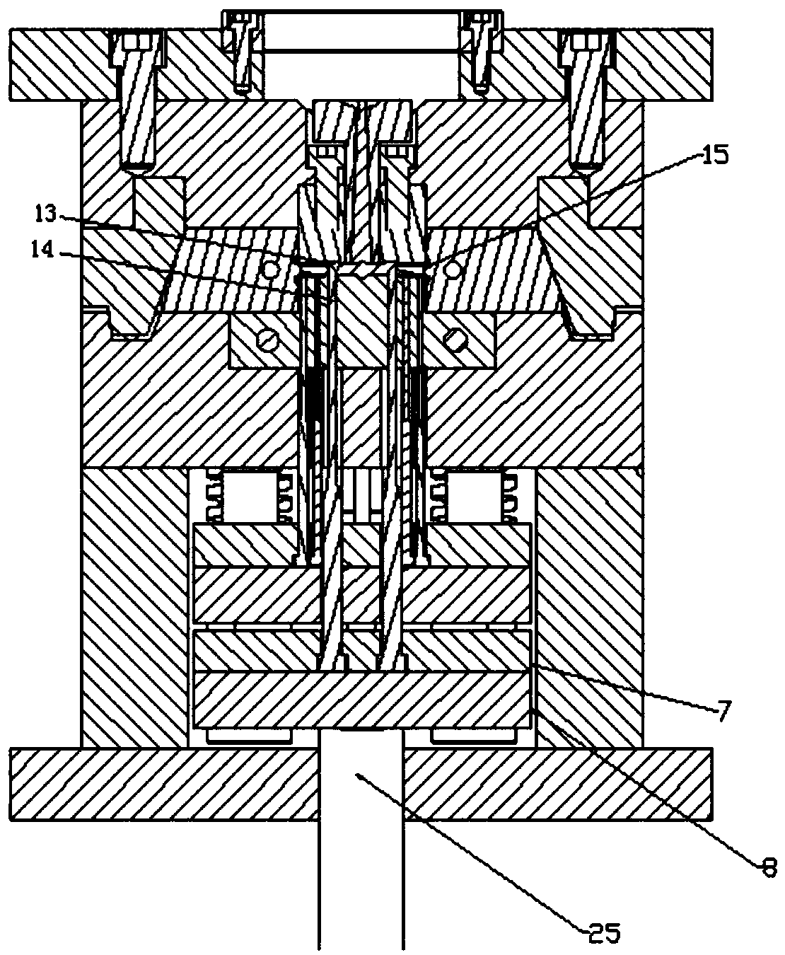
[0031] After the injection, the neutron ejector rod 25 pushes out the second thimble panel 7 and the second thimble bottom plate 8 to drive the cutter 14, and the cutter 14 moves upward to cut off the product 15 and the flow channel 13, as figure 2 shown.

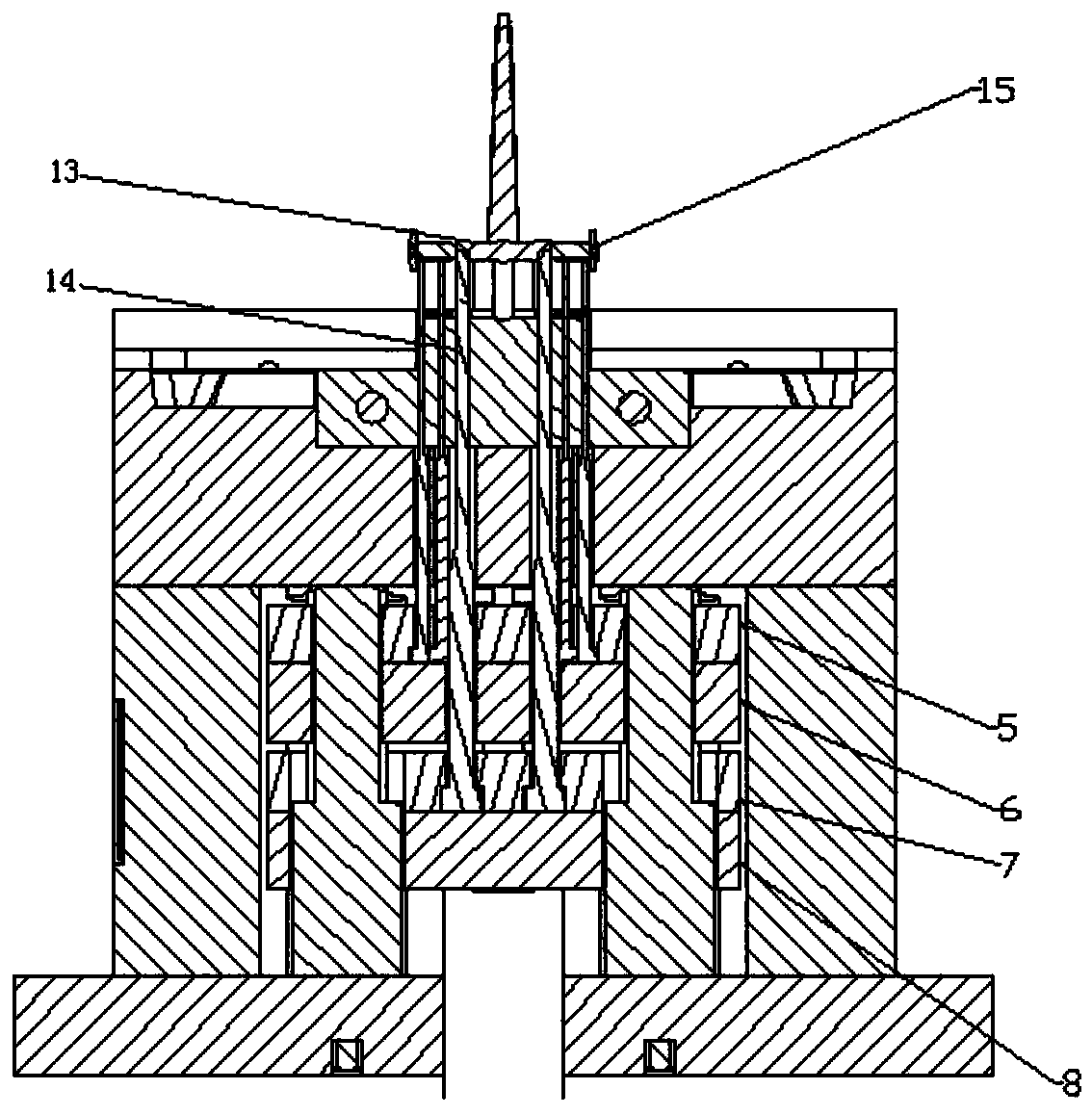
[0032] The second thimble panel 7 and the second thimble base plate 8 move a certain distance and meet the first thimble panel 5 and the first thimble base plate 6 below, and the neutron ejector rod 25 stops moving, because the first thimble panel 5 and the first thimble base plate 6 have Back needle limit can not move without mold opening, so the second thimble panel 7 and the second thimble base plate 8 move a certain distance and will stop moving ...


PUM

PropertyMeasurementUnit
widthaaaaaaaaaa

Abstract

The invention discloses an in-mould hot-cutting automatic sprue cutting mould structure. The mould structure comprises a front mould, a rear mould and a cutting knife advancing assembly; the front mould and a rear mould are mutually assembled; the cutting knife advancing assembly is arranged in the rear mould; a flow channel (13) used for carrying out injection molding on a product (15) is formedbetween the front mould and the rear mould; the tail end of each sprue of the flow channel (13) is connected with a product injection moulding cavity; cutting knives (14) capable of advancing towardsthe sprues are arranged in the cutting knife advancing assembly; and in the injection moulding process, the cutting knife advancing assembly drives each cutting knife (14) in the rear mould to be jacked between each sprue of the flow channel (13) and each product injection moulding cavity, the sprues and the product injection moulding cavities are cut before the product is subjected to cooling moulding, and an in-mould hot-cutting technology of the product is achieved. The automation of in-mould hot-cutting moulding is achieved, unnecessary man-made movement in the production process is avoided, the quality conformance is ensured through completely-automatic mechanical shearing of the product, and the mould structure has the incomparable advantage compared with a traditional mould in the large-scale production process of the product.

Description

technical field [0001] The invention relates to a mold, in particular to a mold structure for hot cutting and automatic gate breaking in the mold. Background technique [0002] In the modern injection molding production process, the requirements for production efficiency and product appearance are getting higher and higher, that is, to improve production efficiency while ensuring product appearance quality requirements. Therefore, it is required that the mold can be produced automatically, that is, the product and the runner are automatically separated when the mold is opened and ejected. Under the existing technology, to achieve the purpose of automatic mold production, there are three ways: latent gate, point gate and hot runner directly pointing on the product, but many products cannot use these three gates due to structure and appearance requirements way, so as not to meet the requirements of automatic production, only the way of side gate glue can be used. The product...

Claims


Application Information

Patent Timeline
Patent Type & Authority Applications(China)
IPC IPC(8): B29C45/38B29C45/26B29C45/27
CPCB29C45/2602B29C45/2708B29C45/38
Inventor 张连
Owner 上海宝鹿车业有限公司
Learn More