
Humidifying structure, indoor unit and air conditioner unit

A technology for indoor units and humid spaces, which is applied in the field of humidification structures, air conditioning units, and indoor units. It can solve the problems of inconvenient installation and maintenance of humidification structures, inability to realize humidification functions alone, and reduced comfort, so as to improve maintenance convenience and improve Efficiency in disassembly and assembly, and the effect of avoiding water leakage

Pending Publication Date: 2018-10-12
GREE ELECTRIC APPLIANCES INC
View PDF8 Cites 6 Cited by
  • Summary
  • Abstract
  • Description
  • Claims
  • Application Information

AI Technical Summary

Problems solved by technology

In some dry areas and dry seasons, such as winter in northern my country, the air is dry when heating with ordinary air conditioners; dry air causes dry skin, damaged respiratory tract, static electricity and other problems, resulting in reduced comfort, while the existing indoor The humidification structure in the machine is integrated inside the indoor unit, that is, the humidification function cannot be realized independently, and it is not convenient to install and maintain the humidification structure

Method used


Image

  • Humidifying structure, indoor unit and air conditioner unit
  • Humidifying structure, indoor unit and air conditioner unit
  • Humidifying structure, indoor unit and air conditioner unit

Examples


Embodiment Construction

[0041] In order to make the object, technical solution and advantages of the present invention clearer, the present invention will be further described in detail below in conjunction with the accompanying drawings and embodiments. It should be understood that the specific embodiments described here are only used to explain the present invention, not to limit the present invention.

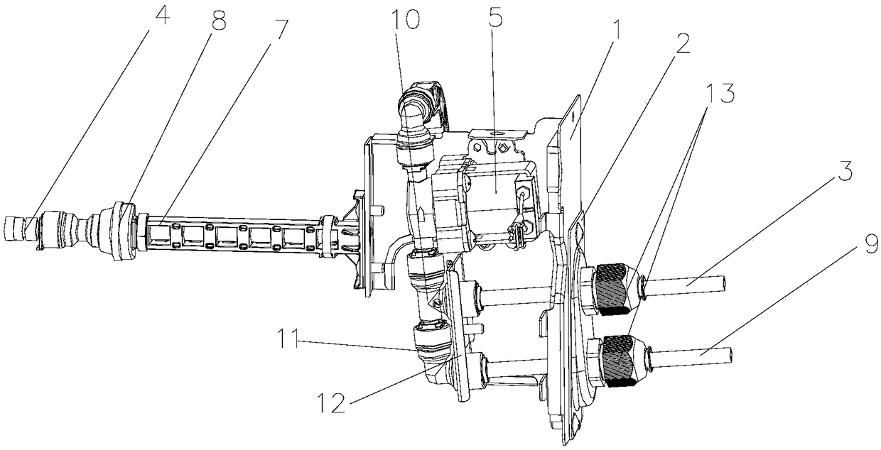
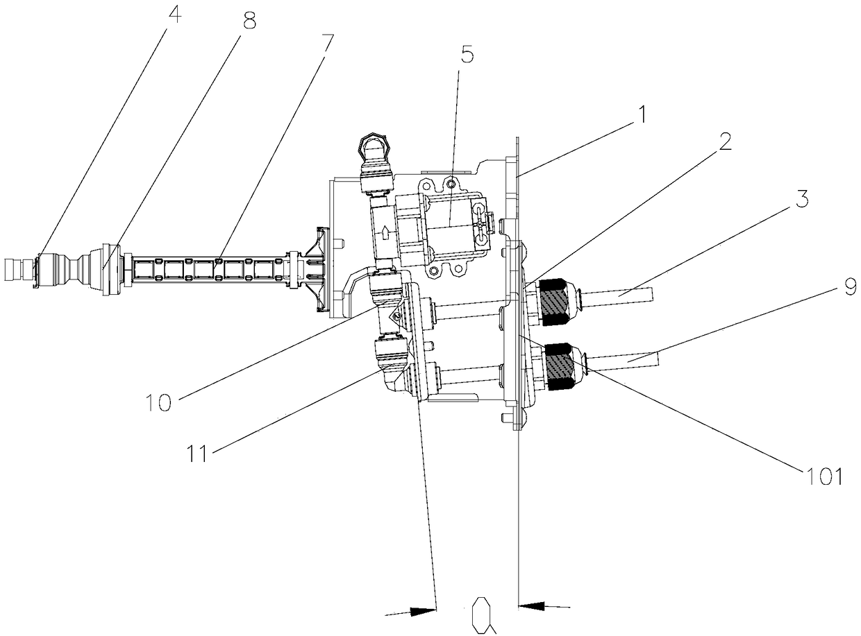
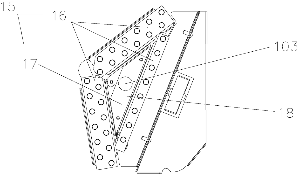
[0042] Such as Figure 1 to Figure 8The humidification structure shown includes a fixed plate 1, a cover plate 2, a water inlet pipe 3 and a humidification assembly 4. The fixed plate 1 is provided with an installation structure for installation with a preset position, and the fixed plate 1 is formed with The installation hole 101, the cover plate 2 is detachably arranged on the installation hole 101, the water inlet pipe 3 protrudes into the fixed plate 1 from one side of the fixed plate 1 in a manner of penetrating the cover plate 2 On the other side of the water inlet pipe 3, the humidifying as...


PUM


Abstract

The invention provides a humidifying structure, an indoor unit and an air conditioner unit. The humidifying structure comprises a fixing plate, a cover plate, a water inlet pipe and a humidifying assembly. According to the humidifying structure, the indoor unit and the air conditioner unit, the cover plate is simply dismounted and mounted on the fixing plate during mounting and repairing, and a water inlet pipe and a water returning pipe can be dismounted and mounted after dismounting the cover plate, and thus the operation step of removing the whole humidifying structure and then replacing apipeline in a traditional dismounting and mounting process is avoided; water pipes in a machine body are kept in inclination structures, so that water cannot flow out of the machine body under the gravity effect in case of water leaking in a connector, and the arraignment of the water pipes in the unit; connecting end ports are prevented from being stressed to cause water leaking; the humidifyingassembly is arranged in the humidifying space and is capable of effectively preventing large water droplets from being directly blown out of the unit or cause potential risk of water leaking; and water from all water outlet positions of a heat exchanger and the humidifying structure can be borne, and thus the problem of water leaking of the indoor unit is avoided.

Description

technical field [0001] The invention relates to the field of air humidity processing equipment, in particular to a humidifying structure, an indoor unit, and an air-conditioning unit. Background technique [0002] With the continuous improvement of living standards, people have higher and higher requirements for air quality indicators, including air humidity requirements. In some dry areas and dry seasons, such as winter in northern my country, the air is dry when ordinary air conditioners are used for heating; dry air causes problems such as dry skin, damaged respiratory tract, static electricity, etc., resulting in reduced comfort. The humidification structure in the machine is integrated inside the indoor unit, that is, the humidification function cannot be realized independently, and it is not convenient to install and maintain the humidification structure. Contents of the invention [0003] In order to solve the above-mentioned technical problems, a humidifying struct...

Claims


Application Information

Patent Timeline
Patent Type & Authority Applications(China)
IPC IPC(8): F24F1/00F24F3/14F24F11/65F24F13/30
CPCF24F1/0007F24F3/14F24F11/65F24F13/30
Inventor 邓朝胜李功瑞余凯薛寒冬刘群波傅英胜许克
Owner GREE ELECTRIC APPLIANCES INC
Learn More