Agricultural unhulled rice drying device

An air-drying device and paddy technology, applied in the direction of drying gas arrangement, drying, dryer, etc., can solve the problems of poor drying effect, insufficient contact between paddy and air, etc., and achieve good drying effect and full contact effect

Pending Publication Date: 2018-10-12
杨冰璐
5 Cites 3 Cited by

AI-Extracted Technical Summary

Problems solved by technology

At present, most of the existing air-drying equipment completes the drying process by blowing a...

Abstract

The invention discloses an agricultural unhulled rice drying device. The upper portion of a device body is fixedly connected with a partition plate; a material storing bucket is arranged on the upperportion of the partition plate; a driving motor is arranged at the upper end of the device body, and is electrically connected with a power source and a switch; the lower portion of the driving motoris rotationally connected with a driving shaft; a bearing of the driving shaft is rotationally connected with the upper portion of the material storing box; the lower portion of the driving shaft is sleeved with the partition plate; the left side of the upper end of the material storing box communicates with a feeding pipe; and the surface of the driving shaft is fixedly connected with a pluralityof stirring rods. According to the device, the driving shaft drives the rotating disk to rotate so that through pipes communicate with material guiding pipes in a reciprocating manner, and an intermittent discharging function is achieved; a rotating conical roller makes unhulled rice falling from the through pipes scattered to the periphery unceasingly, so that the scattered unhulled rice makes sufficient contact with gas in the device body; the upper end of a connection rod drives a movable plate to swing in a reciprocating manner to raise the unhulled rice again and make the unhulled rice be in contact with air in the device body, the unhulled rice drying function is achieved, the unhulled rice makes sufficient contact with air blown in by an air blower, and the drying effect is good.

Application Domain

Technology Topic

Image

  • Agricultural unhulled rice drying device
  • Agricultural unhulled rice drying device
  • Agricultural unhulled rice drying device

Examples

  • Experimental program(1)

Example Embodiment

[0018] The technical solutions in the embodiments of the present invention will be clearly and completely described below in conjunction with the accompanying drawings in the embodiments of the present invention. Obviously, the described embodiments are only a part of the embodiments of the present invention, rather than all the embodiments. Based on the embodiments of the present invention, all other embodiments obtained by those of ordinary skill in the art without creative work shall fall within the protection scope of the present invention.
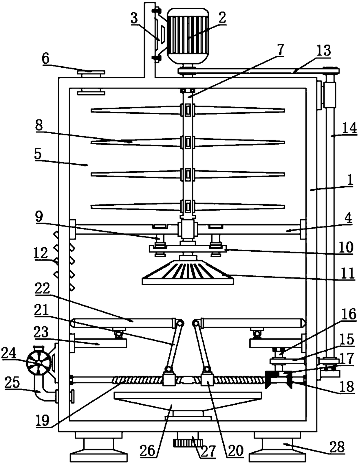
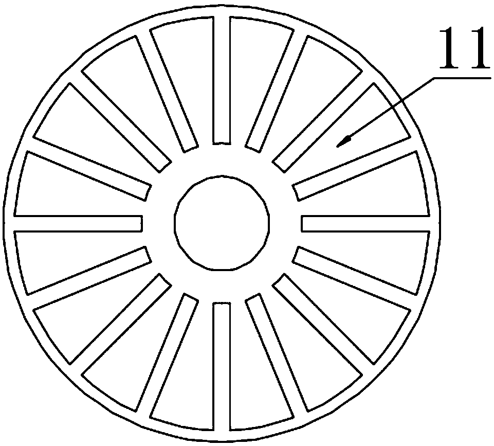
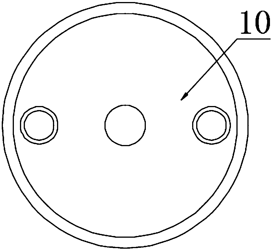
[0019] See Figure 1~3 In the embodiment of the present invention, an agricultural rice drying device includes a device body 1, a partition plate 4, a driving shaft 7, a rotating disk 10, a tapered roller 11, a driven shaft 14, a bevel gear 18, a two-way threaded rod 19, The movable plate 23 and the blower 24; the upper part of the device body 1 is fixedly connected to the partition plate 4, the upper part of the partition plate 4 is provided with a storage bucket 5, and the upper end of the device body 1 is provided with a drive motor 2 which is electrically connected to the power supply and switch, and drives The left side of the motor 2 is fixedly connected to the motor base 3, and the motor base 3 is bolted to the device body 1. The lower part of the driving motor 2 is rotatably connected to the driving shaft 7, and the bearing of the driving shaft 7 is rotatably connected to the upper part of the storage box 5, and the lower part of the driving shaft 7 is fitted Partition plate 4, turn on the switch so that the drive motor 2 is energized to drive the drive shaft 7 to rotate; the upper left side of the storage box 5 is connected to the feed pipe 6, and the surface of the drive shaft 7 is fixedly connected with a plurality of stirring rods 8, on both sides of the partition plate 4 The guide tube 9 is symmetrically arranged, and the upper part of the guide tube 9 is connected to the bottom of the storage box 5, the lower end of the guide tube 9 is attached to the rotating disk 10, the rotating disk 10 is fixedly connected to the driving shaft 7, and the two sides of the rotating disk 10 are symmetrically provided with through pipes , The axis of the through pipe and the guide pipe 9 are on the same vertical line, the lower end of the driving shaft 7 is fixedly connected with the tapered roller 11, the upper surface of the tapered roller 11 is provided with a plurality of raised strips in the circumferential direction, and the rotating driving shaft 7 drives the rotating disk 10 follows the rotation to make the pipe reciprocatingly communicate with the guide tube 9 to realize the intermittent feeding function. At the same time, the active shaft 7 drives the stirring rod 8 to follow the rotation to agitate the rice in the storage box 5 to prevent the rice from being united in the storage box 5 without falling. The driving shaft 7 also drives the tapered roller 11 to rotate, and the rotating tapered roller 11 continuously disperses the rice grains falling from the pipe to the surroundings, so that the scattered rice grains are in full contact with the gas in the device body 1.
[0020] The upper part of the driving shaft 7 is rollingly connected to the left side of the first timing belt 13, and the right side of the first timing belt 13 is rollingly connected to the upper end of the driven shaft 14. The upper part of the driven shaft 14 is fitted with the right end of the sleeve, which is fixedly connected to the outer wall of the device body 1 , And the lower end bearing of the driven shaft 14 is rotatably connected to the support plate, and the support plate is fixedly connected to the device body 1. The rotating driving shaft 7 drives the driven shaft 14 to follow the rotation through the first timing belt 13; The two timing belts 15 are on the right side, the second timing belt 15 passes through the device body 1, the left side of the second timing belt 15 is connected to the shaft 16 in rolling motion, the lower part of the device body 1 is symmetrically provided with a horizontal plate 23 on both sides, and the horizontal plate 23 is fixedly connected to the device body 1. The inner wall and the upper end bearing of the rotating shaft 16 are rotatably connected with the horizontal plate 23, the lower end of the rotating shaft 23 is fixedly connected with a semi-conical gear 17, and the two sides below the semi-conical gear 17 are symmetrically provided with bevel gears 18, and the bevel gear 18 is fixedly connected with a two-way threaded rod 19, a semi-conical gear 17 Half with teeth and half without teeth, half bevel gear 17 has a toothed part meshing with bevel gear 18, rotating driven shaft 14 drives the shaft 16 and half bevel gear 17 to follow rotation through the second timing belt 15, half bevel gear 17 has a toothed part Drive the bevel gears 18 on the left and right sides to reciprocate forward and reverse, and then drive the bidirectional threaded rod 19 to follow the reciprocating forward and reverse rotation; the two ends of the bidirectional threaded rod 19 are connected to the device body 1 by bearing rotation, and the bidirectional threaded rod 19 is provided with collars 20 symmetrically on both sides , The collar 20 is threadedly connected to the two-way threaded rod 19, and the upper end of the collar 20 is rotated to connect to the lower end of the connecting rod 21, the upper end of the connecting rod 21 is rotated to connect to the end of the movable plate 22, the lower surface of the middle of the movable plate 22 is rotated to connect to the horizontal plate 23, reciprocating positive and negative The rotating bidirectional threaded rod 19 drives the collar 20 to reciprocate left and right to drive the lower end of the connecting rod 21 to reciprocate left and right. The upper end of the connecting rod 21 drives the movable plate 22 to reciprocate, and the rice grains dispersed by the tapered roller 11 fall onto the movable plate 22. The swinging movable plate 22 continuously raises the rice grains again, and fully contacts the air in the device body 1.
[0021] A blower 24 is provided outside the left side of the device body 1, the blower 24 is connected to the intake pipe 25, the intake pipe 25 is connected to the inside of the device body 1, and the left side of the device body 1 is fixedly connected to the inclined air pipe 12, and the bottom of the device body 1 is fixedly connected to the hopper 26. The lower end of the receiving hopper 26 is connected to the discharge pipe 27. The bottom of both sides of the device body 1 is symmetrically provided with legs 28. The upper ends of the legs 28 are fixedly connected with the bottom of the device body 1, and the swinging movable plate 22 continuously raises the rice from the middle gap It falls into the receiving hopper 26 and is discharged through the discharge pipe 27. The blower 24 continuously blows external dry air into the dry and humid rice inside the device body 1, and the dry air takes away part of the moisture in the rice and is discharged through the inclined air pipe 12.
[0022] The working principle of the present invention is: turning on the switch makes the driving motor 2 energize to drive the driving shaft 7 to rotate, and the rotating driving shaft 7 drives the rotating disk 10 to follow the rotation, so that the through pipe reciprocates and communicates with the guide tube 9 to realize the intermittent feeding function. 7 At the same time, the stirring rod 8 is driven to follow the rotation to agitate the rice in the storage box 5 to prevent the rice from being united and not falling in the storage box 5. The driving shaft 7 also drives the cone roller 11 to rotate, and the rotating cone roller 11 will pass through The rice falling from the tube is continuously scattered around, so that the scattered rice is in full contact with the gas in the device body 1. The rotating driving shaft 7 drives the driven shaft 14 to follow the rotation through the first timing belt 13, and the rotating driven shaft 14 passes through the The two synchronous belts 15 drive the shaft 16 and the semi-conical gear 17 to follow the rotation. The toothed part of the semi-conical gear 17 drives the bevel gears 18 on the left and right sides to reciprocate forward and reverse, and then drive the two-way threaded rod 19 to follow the reciprocating forward and reverse, and reciprocate forward and reverse. The two-way threaded rod 19 drives the collar 20 to reciprocate left and right to drive the lower end of the connecting rod 21 to move back and forth, and the upper end of the connecting rod 21 drives the movable plate 22 to reciprocate. The rice grains dispersed by the tapered roller 11 fall onto the movable plate 22 and swing The movable plate 22 continuously raises the rice again, fully contacting the air in the device body 1, and the swing movable plate 22 continuously raises the rice from the middle gap and falls down to the receiving hopper 26 to be discharged through the discharge pipe 27, and the blower 24 The external dry air is continuously blown into the dry and humid rice inside the main body 1 of the device, and the dry air takes away part of the moisture in the rice and is discharged through the inclined air duct 12.
[0023] For those skilled in the art, it is obvious that the present invention is not limited to the details of the foregoing exemplary embodiments, and the present invention can be implemented in other specific forms without departing from the spirit or basic characteristics of the present invention. Therefore, from any point of view, the embodiments should be regarded as exemplary and non-limiting. The scope of the present invention is defined by the appended claims rather than the above description, and therefore it is intended to fall within the claims. All changes within the meaning and scope of equivalent elements of are included in the present invention. Any reference signs in the claims should not be regarded as limiting the claims involved.
[0024] In addition, it should be understood that although this specification is described in accordance with the implementation manners, not each implementation manner only includes an independent technical solution. This narration in the specification is only for clarity, and those skilled in the art should consider the specification as a whole The technical solutions in the embodiments can also be appropriately combined to form other implementations that can be understood by those skilled in the art.

PUM

no PUM

Description & Claims & Application Information

We can also present the details of the Description, Claims and Application information to help users get a comprehensive understanding of the technical details of the patent, such as background art, summary of invention, brief description of drawings, description of embodiments, and other original content. On the other hand, users can also determine the specific scope of protection of the technology through the list of claims; as well as understand the changes in the life cycle of the technology with the presentation of the patent timeline. Login to view more.

Similar technology patents

Pot

Owner:青岛瑞迪燃气具制造有限公司

Classification and recommendation of technical efficacy words

  • Good drying effect
  • Fully contacted
Why Eureka
Try Eureka