
Automobile part drying device

A technology for auto parts and drying devices, applied in drying, drying machine, drying gas arrangement and other directions, can solve the problems of uneven drying and uneven heating, reduce drying time, speed up drying, The effect of improving efficiency

Pending Publication Date: 2018-10-12
重庆旺豹商贸有限公司
View PDF8 Cites 0 Cited by
  • Summary
  • Abstract
  • Description
  • Claims
  • Application Information

AI Technical Summary

Problems solved by technology

[0005] The purpose of the present invention is to provide a drying device for auto parts to solve the problem of uneven drying caused by uneven heating in the drying process of auto parts in the prior art

Method used


Image

  • Automobile part drying device
  • Automobile part drying device
  • Automobile part drying device

Examples


Embodiment Construction

[0024] The following is further described in detail through specific implementation methods:

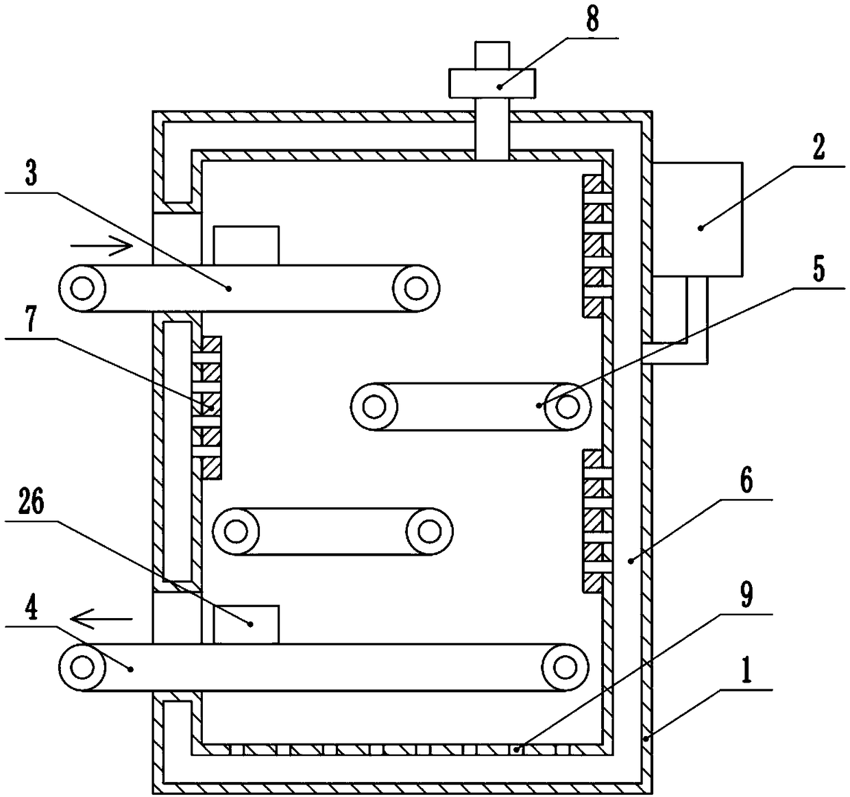
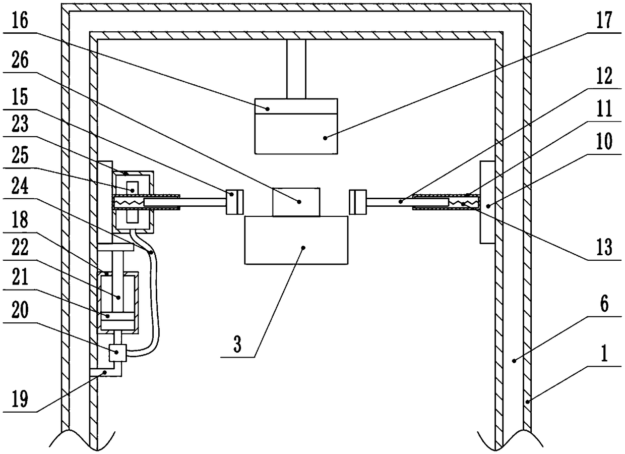
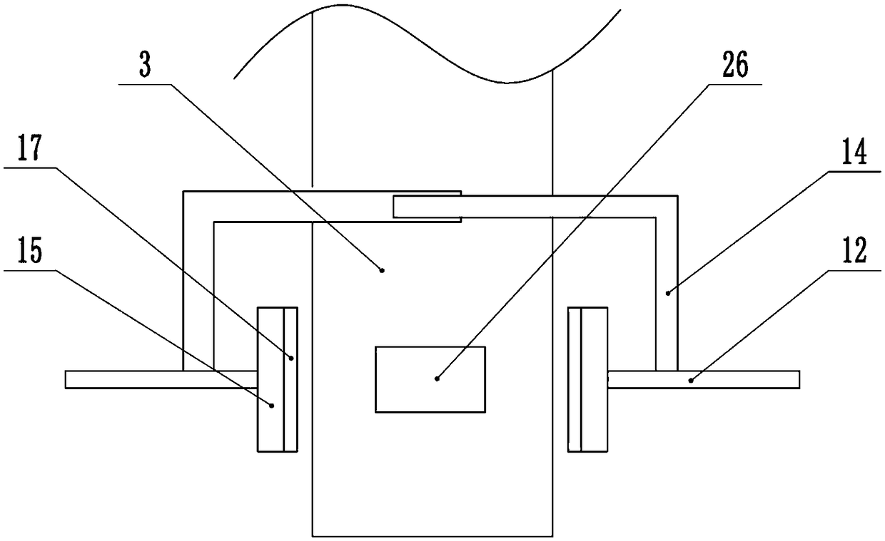
[0025] The reference signs in the accompanying drawings of the description include: drying box 1, air supply box 2, feeding conveying mechanism 3, discharging conveying mechanism 4, intermediate conveying mechanism 5, cavity 6, wind collecting plate 7, second one-way exhaust Valve 8, through hole 9, slide plate 10, outer rod 11, inner rod 12, spring 13, connecting rod 14, electromagnet 15, top plate 16, sponge 17, first cylinder 18, first conduit 19, three-way valve 20. Piston 21, piston rod 22, second cylinder 23, second conduit 24, turbine 25, auto parts 26.

[0026] The embodiment is basically as attached Figure 1 to Figure 3 Shown:

[0027]Drying device for auto parts, including a frame, on which a drying box 1 and an air supply box 2 are fixedly connected. The drying box 1 is provided with a feeding conveying mechanism 3 and a discharging conveying mechanism 4 sequentially fr...


PUM


Abstract

The invention relates to the technical field of automobile part machining and discloses an automobile part drying device. The automobile part drying device comprises a rack. A drying box and an air supply box are arranged on the rack. The driving box is provided with a feed conveying mechanism and a discharge conveying mechanism. An intermediate conveying mechanism is arranged in the drying box. The drying box is provided with a cavity. Air collection plates are arranged in the drying box. A pretreatment mechanism is arranged in the drying box. The pretreatment mechanism comprises sliding plates oppositely arranged on the two sides of the feed conveying mechanism. An outer sleeve rod is rotatably connected to each sliding plate. An inner sleeve rod is in spline connection with each outer sleeve rod. A spring is connected between each inner sleeve rod and the corresponding outer sleeve rod. One end of each inner sleeve rod is fixedly connected with an electromagnet. The two electromagnets are attracted magnetically and are each provided with a water absorption part. A top plate is fixedly connected to the interior of the drying box. The top plate is located above the electromagnets.The side, facing automobile parts, of the top plate is provided with a water absorption part. Through the automobile part drying device, the problem that automobile parts are heated unevenly and dried non-uniformly in the drying process in the prior art is solved.

Description

technical field [0001] The invention relates to the technical field of auto parts processing, in particular to an auto parts drying device. Background technique [0002] During the processing of auto parts, they need to be cleaned to remove dust and stains on the surface of auto parts. After cleaning, in order to facilitate subsequent processing or direct transportation, auto parts need to be dried in time. The traditional drying method is usually to put the auto parts to be dried into the oven, and dry them batch by batch. This method needs to take out the previous batch after drying, and then put them into the next batch. The drying efficiency is relatively high. Low, not suitable for large-scale production and processing. [0003] In order to solve the above problems, the Chinese patent (CN107062863A) discloses a dryer for auto parts, including a base, a motor, a transmission device, a heating device, a hook, a drying box, a temperature sensor and a controller, and a sph...

Claims


Application Information

Patent Timeline
Patent Type & Authority Applications(China)
IPC IPC(8): F26B15/18F26B21/00F26B25/00
CPCF26B15/18F26B21/004F26B25/003
Inventor 谢兴玖
Owner 重庆旺豹商贸有限公司
Learn More