Scanning rack flatness calibration device and calibration method thereof

A calibration device and flatness technology, which is applied to measurement devices, inclinations, instruments, etc., can solve the problems of failing to improve the flatness of the scanning frame, shortening the adjustment period, and expensive calibration equipment, and achieve convenient calibration. Work, shorten the adjustment cycle, the effect of low professional level requirements

Inactive Publication Date: 2018-10-12
南京艾文森电子科技有限公司
View PDF0 Cites 0 Cited by
  • Summary
  • Abstract
  • Description
  • Claims
  • Application Information

AI Technical Summary

Problems solved by technology

[0005] Aiming at the deficiencies of the prior art, the present invention provides a scanning frame flatness calibration device and its calibration method, which solves the problem that the existing scanning frame calibrati

Method used


Image

  • Scanning rack flatness calibration device and calibration method thereof
  • Scanning rack flatness calibration device and calibration method thereof
  • Scanning rack flatness calibration device and calibration method thereof

Examples


Example Embodiment

[0021] The technical solutions in the embodiments of the present invention will be clearly and completely described below in conjunction with the accompanying drawings in the embodiments of the present invention. Obviously, the described embodiments are only a part of the embodiments of the present invention, rather than all the embodiments. Based on the embodiments of the present invention, all other embodiments obtained by those of ordinary skill in the art without creative work shall fall within the protection scope of the present invention.
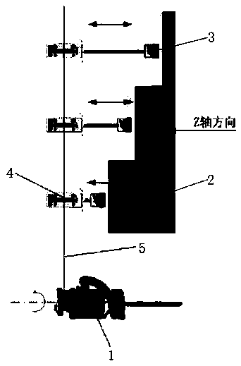
[0022] See Figure 1-4 , The embodiment of the present invention provides a technical solution: a scanning frame flatness calibration device, including a laser transmitter 1 and a Z-axis collection frame 2, a side of the Z-axis collection frame 2 is movably connected with a magnetic table base 3, and magnetic A laser receiver 4 is movably connected to the side of the meter base 3 away from the Z-axis collection frame 2, and the laser tra...


PUM


Abstract

The invention discloses a scanning rack flatness calibration device and relates to the technical field of laser measurement. The device includes a laser emitter and a Z-axis collecting rack; a magnetic surface base is movably connected to one side of the Z-axis collecting rack, a laser receiver is movably connected to the side, away from the Z-axis collecting rack, of the magnetic surface base, and the laser emitter emits rotary laser beams. According to the method, the laser receiver is placed on the Z-axis collecting rack through the magnetic surface base at first. By means of the scanning rack flatness calibration device and the calibration method thereof, the problem that only double theodolites or laser tracing instruments can be adopted for existing measurement of the spatial flatness can be well solved, the prices of the expensive instruments are greatly reduced, and the requirements for the professional level of testers are relatively low, so that the device is extremely suitable for application in small-scale companies. Meanwhile, the adjustment cycle is well shortened, the purpose of improving the flatness of a scanning rack is achieved, and therefore more convenience isprovided for people to calibrate scanning racks.

Description

technical field [0001] The invention relates to the technical field of laser measurement, in particular to a scanning frame flatness calibration device and a calibration method thereof. Background technique [0002] The scanning frame is used to cooperate with the test of the amplitude and phase consistency of each channel of the array antenna. It is a key component in the entire near-field measurement system. For antennas of different frequencies, different precision scanning frames are required. This patent introduces the rotating laser measurement The application of the plane in the flatness calibration process of the scanning frame, using the StatusPro rotating laser measurement system to measure and calibrate the flatness of the scanning frame, has been applied to several scanning frame projects, and the calibration results are compared with the measurement results of the laser tracker , the two measurements are consistent. [0003] At present, the measurement of spati...

Claims


Application Information

Patent Timeline
IPC IPC(8): G01C9/06
CPCG01C9/06G01C2009/066
Inventor 钱金堂
Owner 南京艾文森电子科技有限公司
Why Eureka
Try Eureka