
Display device and vehicle-mounted display system

A display device and vehicle-mounted display technology, applied in optical elements, optics, instruments, etc., can solve the problems of asymmetric and unsatisfactory viewing angles, and achieve the effects of simple structure, low cost, and good viewing angle range.

Inactive Publication Date: 2018-10-12
XIAMEN TIANMA MICRO ELECTRONICS
View PDF6 Cites 1 Cited by
  • Summary
  • Abstract
  • Description
  • Claims
  • Application Information

AI Technical Summary

Problems solved by technology

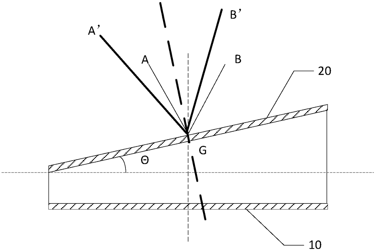
[0003] In the existing HUD design, such as figure 1 As shown, there is a certain gap and angle between the backlight 10 and the display panel 20 (the angle θ in the figure). Since the light of the backlight is strong in a certain range perpendicular to the backlight, the viewing angle of the HUD structure is The range is roughly within the range of AB in the figure (that is, about ±25° in the direction perpendicular to the backlight panel 10), resulting in asymmetric viewing angles in the direction perpendicular to the display panel 20, which cannot meet the relatively good A'B' viewing angle range in the figure. Requirements (that is, the boundary GA' in the figure cannot be reached at the boundary of the viewing angle on the left), because the viewing angle range of A'B' is about ±25° perpendicular to the direction of the display panel 20

Method used


Image

  • Display device and vehicle-mounted display system
  • Display device and vehicle-mounted display system
  • Display device and vehicle-mounted display system

Examples


Embodiment Construction

[0024] The following will clearly and completely describe the technical solutions in the embodiments of the present invention with reference to the accompanying drawings in the embodiments of the present invention. Obviously, the described embodiments are only some of the embodiments of the present invention, not all of them. Based on the embodiments of the present invention, all other embodiments obtained by persons of ordinary skill in the art without creative efforts fall within the protection scope of the present invention.

[0025] An embodiment of the present invention provides a display device, including a backlight board and a display panel, the backlight board is surrounded by side walls, the side walls and the backlight board form a cavity with an open top, and the display panel is arranged on The top is opened and the cavity is closed, and it is characterized in that,

[0026] The backlight panel is arranged parallel to the first direction, the display panel is arra...


PUM


Abstract

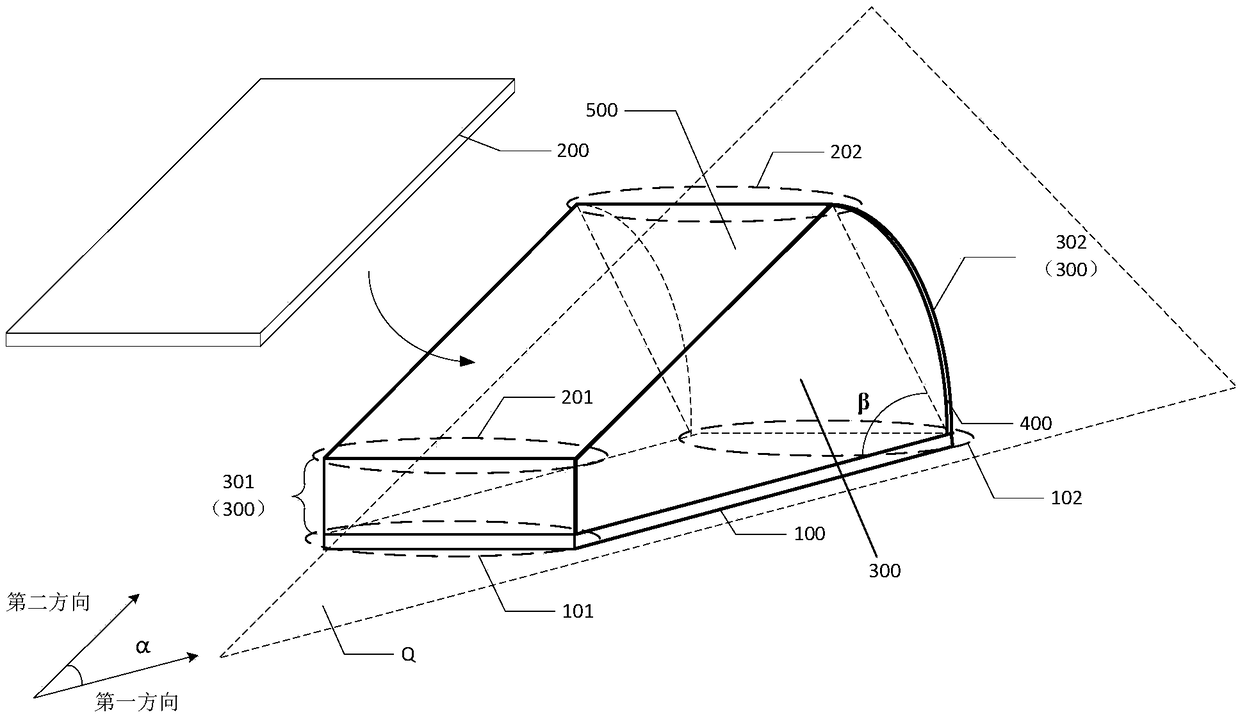
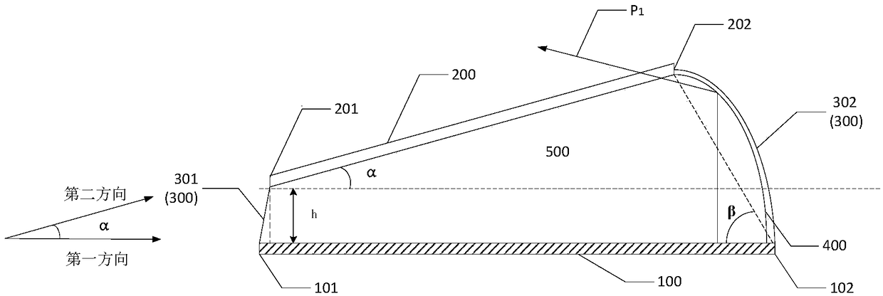
The invention discloses a display device and a vehicle-mounted display system. The display device comprises a backlight board, a display panel and side walls. The backlight board is arranged in a wayof being parallel to the first direction. The display panel is arranged in a way of being parallel to the second direction. The inclined angle between the backlight board and the display panel is an acute angle. The backlight board comprises a first end and a second end in turn in the first direction. The display panel comprises a third end and a fourth end in turn in the second direction. The inclined angle between the plane connecting the second end and the fourth end and the plane of the backlight board is an acute angle. The side walls comprise a first side wall and a second side wall. Thefirst side wall is connected with the first end and the third end. The second side wall is connected with the second end and the fourth end. The second side wall comprises a reflection structure. With application of the display device and the vehicle-mounted display system of the structure, the display device is enabled to present great viewing angle range, the asymmetry of the viewing angle perpendicular to the display panel direction can be reduced, the structure is simple and the cost is low.

Description

technical field [0001] The invention relates to the field of display technology, in particular to a display device and a vehicle-mounted display system including the display device. Background technique [0002] Head Up Display (Head Up Display, hereinafter referred to as HUD), is gradually being used in vehicle display devices. The principle of the vehicle HUD display system in the prior art is to use a display panel to project the displayed content on the car's front door through various devices. On the windshield, the driver can see various information such as instrument parameters without looking down while driving. [0003] In the existing HUD design, such as figure 1 As shown, there is a certain gap and angle between the backlight 10 and the display panel 20 (the angle θ in the figure). Since the light of the backlight is strong in a certain range perpendicular to the backlight, the viewing angle of the HUD structure is The range is roughly within the range of AB in ...

Claims


Application Information

Patent Timeline
Patent Type & Authority Applications(China)
IPC IPC(8): G02B27/01
CPCG02B27/0101G02B27/0149
Inventor 陈娜森方丽婷吴玲沈柏平
Owner XIAMEN TIANMA MICRO ELECTRONICS
Learn More