A visual recognition device and method suitable for placement machines

A technology of visual recognition and placement machine, which is applied in the direction of assembling printed circuits, printed circuits, and electrical components with electrical components. Efficiency, accurate and fast component placement, and easy operation

Active Publication Date: 2020-05-01
安徽广晟德自动化设备有限公司
View PDF5 Cites 0 Cited by
  • Summary
  • Abstract
  • Description
  • Claims
  • Application Information

AI Technical Summary

Problems solved by technology

[0008] The first method of manual identification has two main disadvantages, one is low efficiency, there are identification errors, and labor costs are required; the other is that now is the era of Industry 4.0, mechanical equipment must be intelligent and suitable for automated assembly line production; the second method Generally, the recognition cameras are installed on the front or side of the suction head assembly. Taking the installation in front of the suction head assembly as an example, a larger front and rear space is required to identify the component position coordinates; similarly, a larger camera is required to place it on the side Left and right space, so there is no effective use of space for structural design, and there are disadvantages of wasting materials and costs

Method used


Image

  • A visual recognition device and method suitable for placement machines
  • A visual recognition device and method suitable for placement machines
  • A visual recognition device and method suitable for placement machines

Examples


Embodiment 1

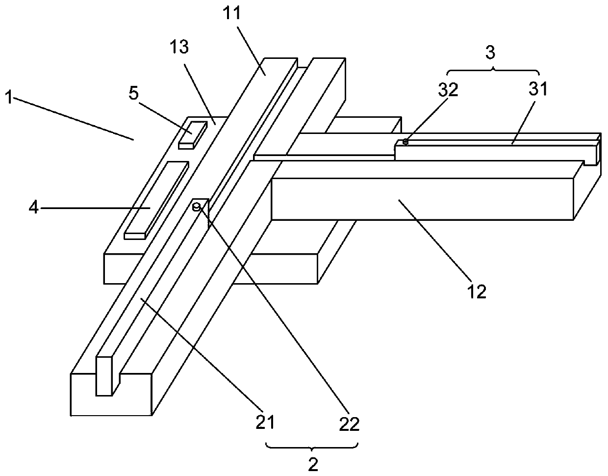
[0040] Example one: such as Figure 1 to 3 As shown, it is only one of the embodiments of the present invention. In order to achieve the effect of better visual recognition of the position of the component, a visual recognition device suitable for placement machine is proposed, which includes a placement channel 1, a component transmission part 2 and a material The transfer part 3, the patch channel 1 is provided with a first transfer rail 11, a second transfer rail 12, and a patch cavity 13 provided at the junction of the first transfer rail 11 and the second transfer rail 12. The patch channel 1 is provided with a magnetic member 4 and a calculation unit 5. The component transmission part 2 includes a first sliding rod 21 extending along the extension direction of the first transmission rail 11 and a first sliding rod 21 arranged on the first sliding rod 21 The first magnetic induction member 22, the material transport portion 3 includes a second sliding rod 31 extending alon...

Embodiment 2

[0050] Embodiment two: such as Figure 4 Shown is only one of the embodiments of the present invention. In order to facilitate the understanding of a visual recognition device suitable for placement machines, the present invention provides a visual recognition method suitable for placement machines. A feeding management device suitable for placement machines. The device includes a placement channel, a component transmission part and a material transmission part. The method includes the following steps:

[0051] S1: Set the first magnetic induction part on the first sliding rod of the element transmission part, and set the second magnetic induction part on the second sliding rod of the material transmission part to ensure that both the first magnetic induction part and the second magnetic induction part are located on the patch channel. Within the magnetic field range;

[0052] It is ensured that the first magnetic induction element and the second magnetic induction element move in ...


PUM


Abstract

The invention provides a visual recognition device and method suitable for a surface mounting machine,and relates to the technical field of surface mounting machines. The visual recognition device suitable for the surface mounting machine comprises a surface mounting channel,a component conveying part and a material conveying part; the surface mounting channel is provided with a first transmissionrail,a second transmission rail,a surface mounting cavity formed in the junction of the first transmission rail and the second transmission rail,and a magnetic piece and a calculation unit are arranged on the surface mounting channel; the component conveying part comprises a first sliding rod and a first magnetic sensing piece arranged on the first sliding rod; the material conveying part comprises a second sliding rod and a second magnetic sensing piece arranged on the second sliding rod,and the first magnetic sensing piece and the second magnetic sensing piece are arranged within a magneticfield range of the magnetic piece. The visual recognition device and method suitable for the surface mounting machine are high in recognition precision and convenient to operate,the coordinate positions of a plurality of components can be simultaneously recognized,the coordinate positions of the components and surface mounting heads can also be simultaneously recognized,and the components are subjected to surface mounting more accurately.

Description

Technical field [0001] The invention relates to the technical field of placement machines, [0002] In particular, the present invention relates to a visual recognition device and method suitable for placement machines. Background technique [0003] Mounter: also known as "mounter" and "surface mount system". In the production line, it is configured after the tin tin machine or printing machine, and the surface mount components are accurately placed on the PCB by moving the mounting head A device on the pad. Divided into two kinds of manual and automatic. [0004] At present, there are mainly the following two methods for the domestic similar visual recognition component coordinate position technology: [0005] The first visual recognition method requires human recognition; [0006] The second way of visual recognition is to use the camera to recognize, and most of the way the camera is installed is that the lens surface is parallel to the work surface. [0007] However, the above two...

Claims


Application Information

Patent Timeline
Patent Type & Authority Patents(China)
IPC IPC(8): H05K13/08H05K13/04H05K3/30
CPCH05K3/303H05K13/0465H05K13/08H05K2203/168
Inventor 胡稳张先文符永胜舒恒
Owner 安徽广晟德自动化设备有限公司
Why Eureka
Try Eureka