
Annular cleaning equipment used for ocean engineering platform

A technology for cleaning equipment and marine engineering, which is applied in the directions of cleaning methods using liquids, cleaning methods using gas flow, cleaning methods and utensils, etc. It can solve the problems of dangerous work efficiency, manual operation, low performance, etc., to expand the cleaning area. Effect

Inactive Publication Date: 2018-10-16
苏州格目文化传媒有限公司
View PDF11 Cites 0 Cited by
  • Summary
  • Abstract
  • Description
  • Claims
  • Application Information

AI Technical Summary

Problems solved by technology

However, the existing cleaning of offshore platform piles requires manual operation in the actual operation process, and the operation on the sea surface has certain dangers and low work efficiency.

Method used


Image

  • Annular cleaning equipment used for ocean engineering platform
  • Annular cleaning equipment used for ocean engineering platform
  • Annular cleaning equipment used for ocean engineering platform

Examples


Embodiment 1

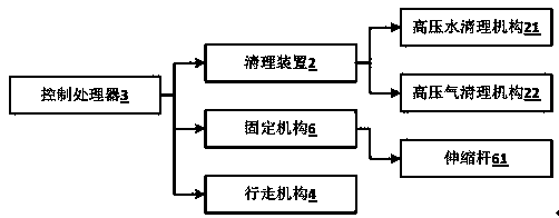
[0027] refer to figure 1 , figure 1 It is a system connection diagram of a ring-shaped cleaning device used for offshore engineering platforms provided by the present invention.

[0028] A circular cleaning device for offshore engineering platforms, comprising: a body 1 , a cleaning device 2 , and a control processor 3 .

[0029] The main body 1 is annular, and the inner side of the main body 1 is provided with a traveling mechanism 4, which is connected with the control processor 3, and the control processor 3 outputs a walking signal to the traveling mechanism 4, and the traveling mechanism 4 moves according to the walking signal. The traveling mechanism 4 can be a crawler belt or a roller, and the traveling mechanism 4 is driven by a control signal output by the control to move in a designated direction. The walking signal output to the running mechanism 4 may include the walking direction and distance, and the running mechanism 4 moves to a designated position according ...

Embodiment 2

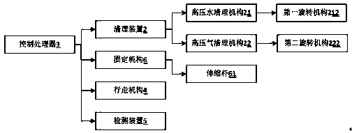
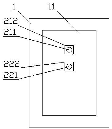
[0035] refer to Figure 2-3 , figure 2 The system connection diagram of the second annular cleaning equipment used for offshore engineering platforms provided by the present invention; image 3 It is a schematic diagram of the second ring-shaped cleaning equipment used for offshore engineering platforms provided by the present invention.

[0036] This embodiment is basically the same as the first embodiment above, except that, preferably, the main body 1 has an inner groove 11 . The high-pressure water cleaning mechanism 21 also includes a water outlet 211 , and the water outlet 211 is disposed in the groove 11 . The high-pressure air cleaning mechanism 22 also includes an air outlet 221 , and the air outlet 221 is disposed in the groove 11 . The groove 11 is disposed on the body 1 and is recessed inward, and the space formed between the groove 11 and the surface of the object can be a working space. The water outlet 211 and the air outlet of the high-pressure water clean...


PUM


Abstract

The invention relates to annular cleaning equipment used for an ocean engineering platform. The equipment comprises a body, a cleaning device and a control processor. The body is annular, a travellingmechanism is arranged on the inner side of the body and connected with the control processor, the control processor outputs a travelling signal to the travelling mechanism, and the travelling mechanism moves according to the travelling signal. The body is further provided with a fixing mechanism, the fixing mechanism comprises at least three telescopic rods and adhesive pieces fixed to one ends of the telescopic rods, the other ends of the telescopic rods are connected with the body, and the telescopic rods are further electrically connected with the control processor. The cleaning device isarranged in the body and comprises a high-pressure water cleaning mechanism and a high-pressure air cleaning mechanism which are both connected with the control processor; and the control processor outputs a cleaning signal to the high-pressure water cleaning mechanism, and the high-pressure water cleaning mechanism sprays out high-pressure water columns so as to clean the surfaces of objects.

Description

technical field [0001] The invention relates to ocean platform cleaning equipment, in particular to an annular cleaning equipment used for ocean engineering platforms. Background technique [0002] With the development of the offshore oil industry, there are more and more large-scale offshore oil facilities such as offshore oil platforms and FPSO. Long-term erosion. At the same time, the marine organisms on the bottom of the jacket and the platform lead to an increase in the overall actual load of the equipment. When the thickness of the dirt is about 2 to 3 cm, the weight of the shell exceeds 50 kg per cubic meter, which makes the stability of the platform and The ability to resist storms is reduced. Once severe natural disasters such as typhoons, tsunamis, and ice disasters occur, it is very easy to bring safety hazards to operators on offshore platforms. Therefore, it is of great significance to clean offshore oil facilities reasonably and effectively. However, the exis...

Claims


Application Information

Patent Timeline
IPC IPC(8): B08B3/02B08B5/02
CPCB08B3/02B08B5/02
Inventor 顾健
Owner 苏州格目文化传媒有限公司
Learn More