Hydraulic bulging tube with partially thickened wall thickness and forming method of hydraulic bulging tube

A hydraulic bulging and partial technology, applied in the field of hydraulic bulging of pipe fittings, can solve the problems of no local thickening of hydroformed parts, no involvement of hydraulic bulging tube design and forming methods, etc.

Inactive Publication Date: 2018-10-16
BAOSHAN IRON & STEEL CO LTD
View PDF9 Cites 4 Cited by
  • Summary
  • Abstract
  • Description
  • Claims
  • Application Information

AI Technical Summary

Problems solved by technology

[0005] Therefore, based on the analysis of the above patents, it can be seen that these patents involve hydroforming parts without local thickening characteristics, and the tube blank is a round tube of equal thickness, and do not involve a hydraulic bulging tube design and forming method with local wall thickness thickening

Method used


Image

  • Hydraulic bulging tube with partially thickened wall thickness and forming method of hydraulic bulging tube
  • Hydraulic bulging tube with partially thickened wall thickness and forming method of hydraulic bulging tube
  • Hydraulic bulging tube with partially thickened wall thickness and forming method of hydraulic bulging tube

Examples


Embodiment 1

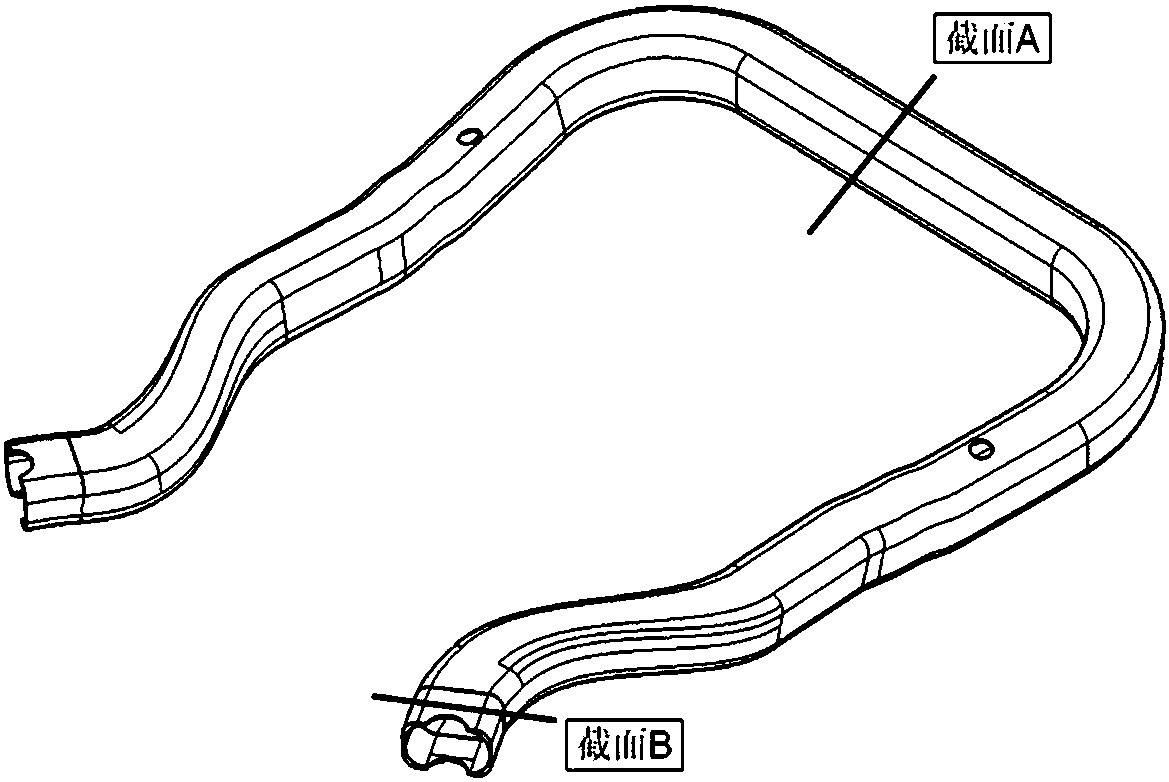
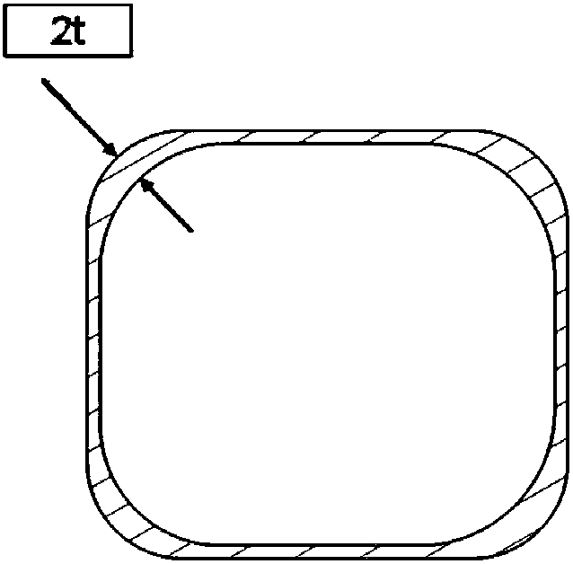
[0068] A kind of hydroforming of pipe fittings with thickened wall thickness at the R angle position of the cross section, such as Figure 1 ~ Figure 3 As shown, where t is 2.0mm, the wall thickness increases at the four R corners. Specifically, for the convenience of subsequent forming mold processing, the wall thickness increases toward the inner side of the tube. This wall thickening feature is present throughout the length of the pipe.

[0069] The subframe tube blank is as Figure 4 , Figure 5 As shown, the section of the tube blank is rectangular, which is an aluminum alloy tube of equal cross-section formed by the extrusion process, and the wall thickness thickening feature is realized through the extrusion process at the four R angle positions of the rectangular tube blank.

[0070] The tube blank is bent by CNC pipe bending, such as Image 6 , Figure 7 The schematic diagram after the pipe bending is shown, and the pipe bending mold is designed according to the s...

Embodiment 2

[0077] A pipe torsion beam with thickened wall thickness at the stress concentration position, such as Figure 10 ~ Figure 13 As shown, the torsion beam can be divided into three parts, the middle section is V-shaped, such as section E, the two ends are rectangular, such as section G, and the middle is a transition section.

[0078] The torsion beam is the main part of the semi-independent rear suspension. It is subjected to bending and torsion during the operation of the car, and the service conditions are harsh. Generally, the stress concentration of the torsion beam occurs at the upper part of the U-shaped groove in the transition section. In this case, for example Image 6 As shown, where t is 2.5mm, the wall thickness at the corresponding stress concentration position is 1.5 times thicker, and gradually disappears to both sides. The wall thickness thickening feature exists in the entire length direction of the pipe fitting, as shown in Image 6 , the corresponding positio...


PUM


Abstract

The invention relates to a hydraulic bulging tube with the partially thickened wall thickness and a forming method of the hydraulic bulging tube. The tube is characterized in that the wall thickness of the upper part or all R angle positions of the circumferential direction of the section of a hydraulic bulging tube body perpendicular to the axis and in the axial direction is larger than the wallthickness of the side wall of the tube body, or / and, the wall thickness of the tube body in the stress concentration position is increased, and the thickened wall thickness is continuous in the axialdirection of the tube body; and the wall thickness of the R angle position is 1.2t to 6.0t, wherein t is the wall thickness mm of the side wall of the tube body. Through the design of the hydraulic bulging tube with the partially thickened wall thickness, the rigidity of the section of a part can be improved, the stress concentration can be improved, and the thickness of a tube blank in the R angle and the corresponding stress concentration position is increased, and therefore, the phenomenon that the wall thickness is excessively thinned and crack occurs due to the fact that the local bulging amount is relatively large can be effectively avoided.

Description

technical field [0001] The invention relates to the field of hydraulic bulging of pipe fittings, in particular to a hydraulic bulging pipe with thickened local wall thickness and a forming method thereof. Background technique [0002] The hydroforming technology of pipe fittings is suitable for processing hollow variable cross-section lightweight components, and has been widely used in the fields of automobiles, aviation, and aerospace. The cross-sectional shapes of hydroformed parts are various, including circular, oval, rectangular, V-shaped, U-shaped, etc. Among them, the rectangular cross-section is a better choice for the cross-section of hydroformed parts because of its high cross-section stiffness. [0003] At present, multi-step bending or rolling circular steel pipes are mostly used in the processing of tube blanks for hydroforming parts. The circular cross-section tube is relatively easy to bend, but when the local bulging of the part is large, it is easy to cause ...

Claims


Application Information

Patent Timeline
Patent Type & Authority Applications(China)
IPC IPC(8): B21D26/033B21D53/88B62D21/00F16L9/02
CPCB21D26/033B21D53/88B62D21/00F16L9/02
Inventor 逯若东陈新平蒋浩民胡晓苏海波王娜
Owner BAOSHAN IRON & STEEL CO LTD
Why Eureka
Try Eureka