Concrete block repairing and cutting device

A concrete block and coagulation technology, which is applied in the direction of ceramic molding machines and manufacturing tools, can solve the problems of burrs or flashes in batches of concrete blocks, affecting the production progress, affecting the cutting quality of blocks, etc., and avoiding overall cutting The effect of quality, ease of use, and simple structure

Inactive Publication Date: 2018-10-16
刘阳国
View PDF0 Cites 2 Cited by
  • Summary
  • Abstract
  • Description
  • Claims
  • Application Information

AI Technical Summary

Problems solved by technology

[0002] After the concrete block is completed, it needs to be cut and trimmed. The process of cutting the concrete block is: first place the whole block on the conveyor, and then the conveyor moves to the cutting machine with the block. The cutting machine first cuts the concrete horizontally through multiple horizontal steel wires, and then the conveyor conveys the concrete blocks to the bottom of the vertical steel wires to stop, and the multiple vertical steel wires move downward to cut the blocks vertically. When cutting the block, one of the horizontal steel wires or the vertical steel wires will be broken during the cutting process, resulting in the inability of the concrete to be cut through, leaving an incomplete cutting seam. The existing treatment The method is to stop the cutting machine, withdraw the steel wire of the cutting machine from the concrete block, and then the workers continue to connect the disconnected steel wire to cut the block again, so that the cutting machine needs to be started again, which affects the production progress. In addition, due to Cutting is to use multiple steel wires to cut synchronously. During the second cutting, the trajectory of the second cutting is easy to be staggered from the trajectory of the first cutting, resulting in burrs or flashes in batches of concrete blocks, which affects the quality of block cutting.

Method used


Image

  • Concrete block repairing and cutting device
  • Concrete block repairing and cutting device
  • Concrete block repairing and cutting device

Examples


Embodiment Construction

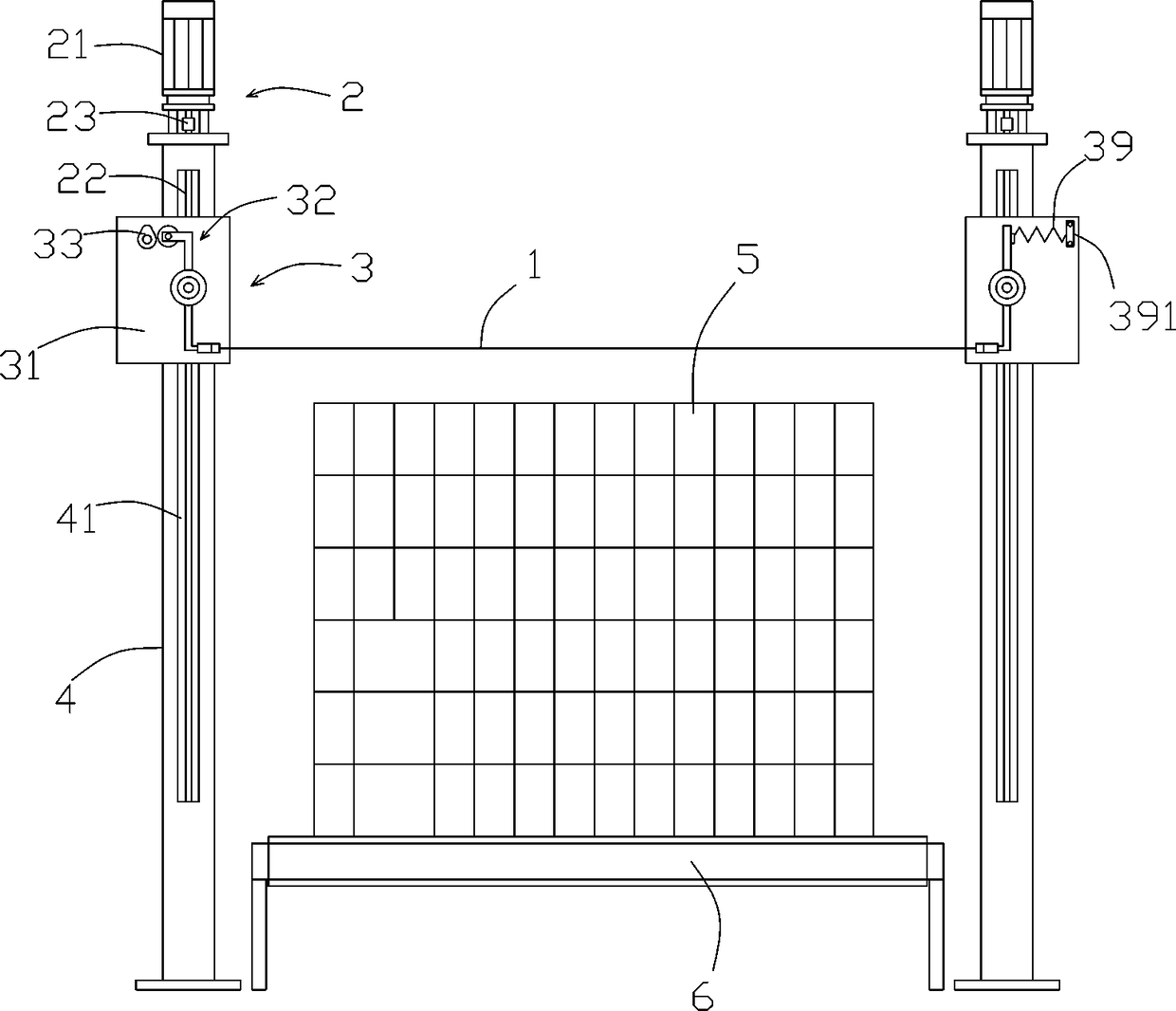
[0021] Such as figure 1 with 4 Shown: a concrete block 5 complementary cutting device, including steel wire 1 and two sets of cutting mechanisms arranged symmetrically on both sides of the concrete block;

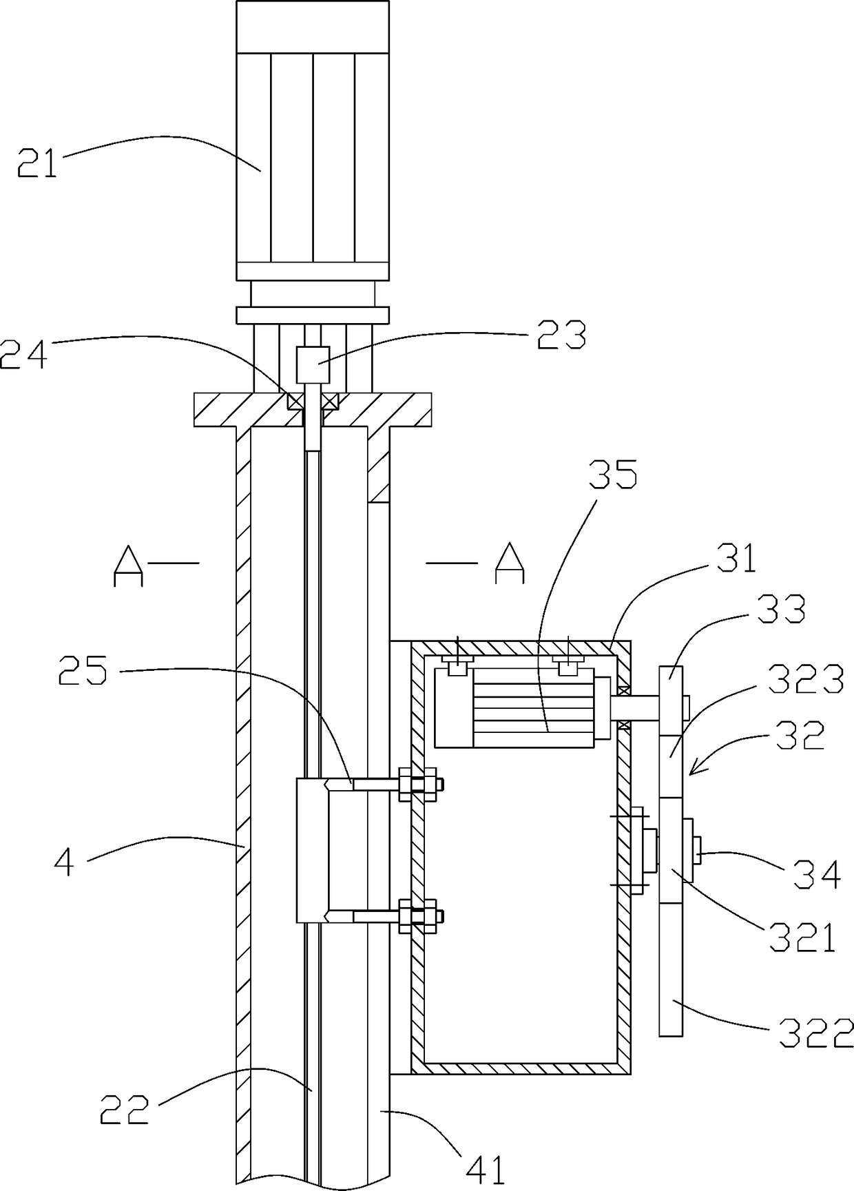
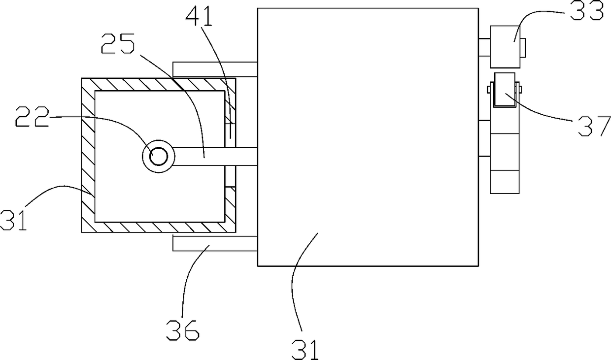
[0022] The cutting mechanism includes a pole 4 and a lifting part 3 and a driving part 2 installed on the pole 4;

[0023] The interior of the pole 4 is hollow, the cross-sectional shape can be square, and one side of the pole 4 has a vertical opening 41;

[0024] The driving part 2 includes a first motor 21 and a ball screw 22 installed on the upper end of the vertical rod 4, bearings 24 are installed on the upper and lower ends of the vertical rod 4, and the two ends of the screw of the ball screw 22 are respectively connected to the upper end of the vertical rod 4 and the lower end of the vertical rod 4. On the bearing 24 at the lower end (the bearing 24 at the lower end of the vertical rod 4 is not shown in the figure), the rotating shaft of the first motor 21 is conn...


PUM


Abstract

The invention provides a concrete block repairing and cutting device. The concrete blocking repairing and cutting device comprises a steel wire and two sets of cutting mechanisms symmetrically arranged on the two sides of a concrete block; vertical rods are internally hollow, and one sides of the vertical rods are provided with vertical openings; each driving part comprises a first motor arrangedat the upper end of the vertical rod and a ball screw connected in the vertical rod in a shaft mode, and first motor rotating shafts are connected with screws in ball screws, and each lifting part comprises a shell, the shells are connected with nuts in the ball screws through a plurality of connecting rods, wing plates are fixedly arranged on the two sides of the shells, the vertical rods are located between the two wing plates, shaft rods are fixed on the end faces of the shells, rocker arms are installed on the shaft rods, and the two ends of the steel wire are connected to the lower ends of the rocker arms in two sets of cutting mechanisms; and a second motor is arranged in the shell of one set of cutting mechanism, a second motor rotating shaft penetrates out of the shell and then isconnected with a cam, and the cam is used for pushing the rocker arms to swing left and right.

Description

technical field [0001] The invention relates to a device for supplementary cutting of concrete blocks. Background technique [0002] After the concrete block is completed, it needs to be cut and trimmed. The process of cutting the concrete block is: first place the whole block on the conveyor, and then the conveyor moves to the cutting machine with the block. The cutting machine first cuts the concrete horizontally through multiple horizontal steel wires, and then the conveyor conveys the concrete blocks to the bottom of the vertical steel wires to stop, and the multiple vertical steel wires move downward to cut the blocks vertically. When cutting the block, one of the horizontal steel wires or the vertical steel wires will be broken during the cutting process, resulting in the inability of the concrete to be cut through, leaving an incomplete cutting seam. The existing treatment The method is to stop the cutting machine, withdraw the steel wire of the cutting machine from ...

Claims


Application Information

Patent Timeline
Patent Type & Authority Applications(China)
IPC IPC(8): B28B11/14
CPCB28B11/14
Inventor 刘阳国
Owner 刘阳国
Why Eureka
Try Eureka