
Retracting rope device of hollow glass with built-in shutter

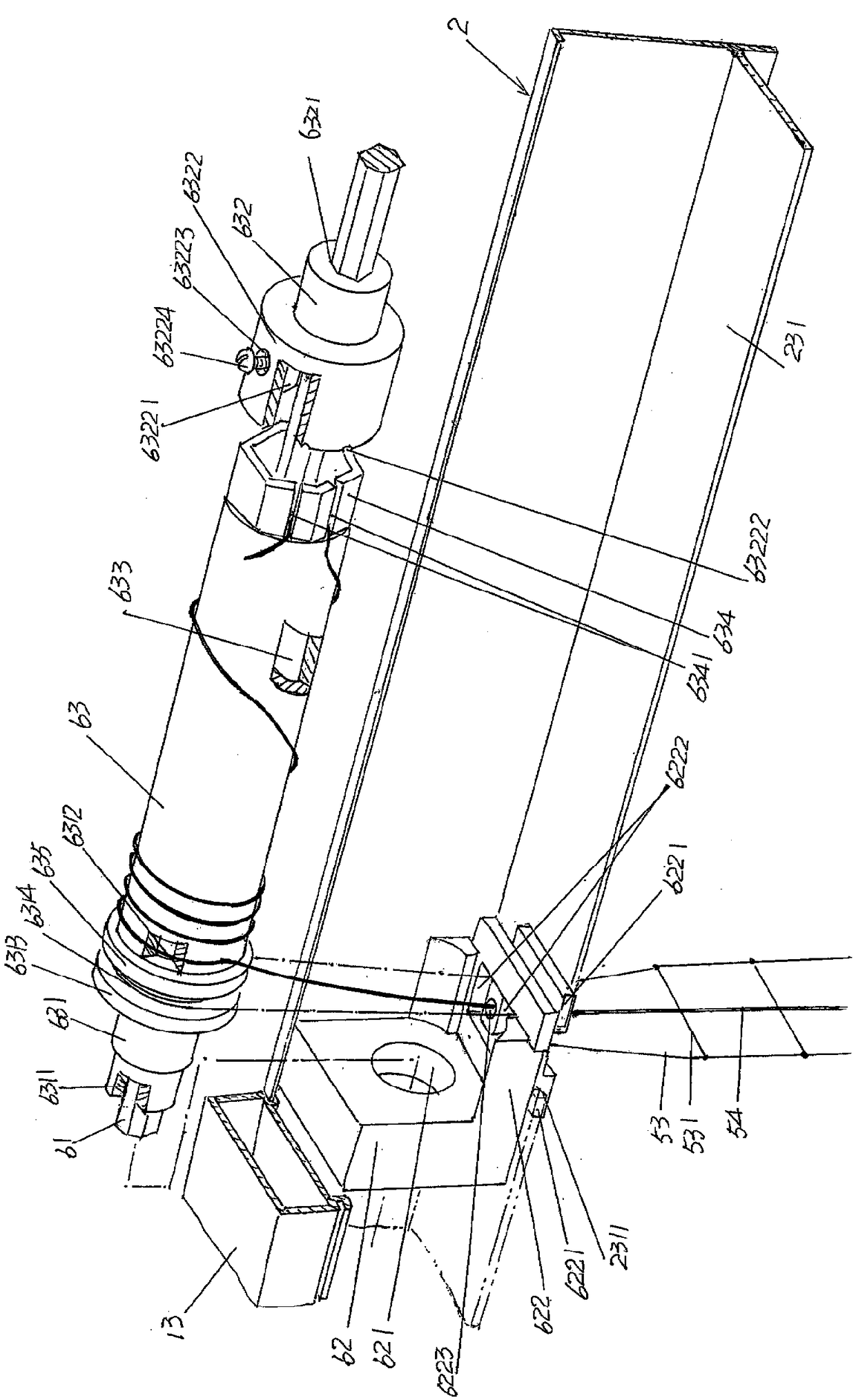
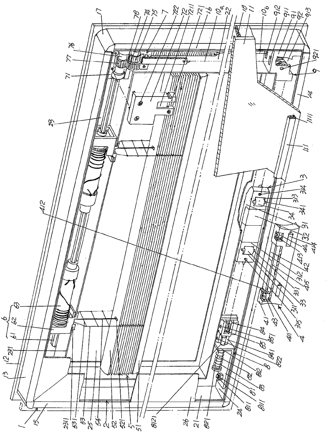
A blinds and retractable rope technology, which is applied to door/window protection devices, windows/doors, building components, etc., can solve the problem of many inflection points of the blind lifting traction rope, insufficient protection of the rollers of the blind lifting traction rope, and poor lifting stability And other problems, to achieve the effect of reducing the probability of damage or even fracture, good lifting stability, good operation and labor saving

Pending Publication Date: 2018-10-16
JIANGSU SDL ENERGY CONSERVATION TECH CO LTD
View PDF19 Cites 0 Cited by
  • Summary
  • Abstract
  • Description
  • Claims
  • Application Information

AI Technical Summary

Problems solved by technology

[0004] Curved patents such as the "bottom control hollow shutter" recommended by CN105003184B objectively have the technical effect recorded in the 0018th paragraph of the description, but there are still four shortcomings in the following aspects: First, due to the connection between one end and the bottom bar ( The other end of the fixedly connected venetian blind lifting traction rope needs to pass through the traction rope give way hole set on the slats, the turning drum guide wheel on the venetian blind driving guide seat, and the venetian blind lifting rope. The traction rope transition wheel, the venetian blind lifting traction rope reversing wheel and the traction slide seat guide wheel of the controller return to the base and are fixed with the base (see paragraphs 0038 to 0042 of the specification of this patent), so that each lifting or descending Once the venetian blind is pulled, the venetian blind traction rope will rub once with the aforementioned turning drum guide wheel, venetian blind lifting and lowering traction rope transition wheel, venetian blind lifting and lowering traction rope reversing wheel and traction slide guide wheel, so it is not enough to truly and effectively protect the venetian blind Lifting traction rope and related wheels; second, due to the many inflection points of the blind lifting traction rope, the lifting stability is relatively poor and the operation is relatively laborious; third, because the blind lifting traction rope sleeve is placed on the flip drum guide wheel, The transition guide wheel of the venetian blind traction rope, the reversing wheel of the venetian blind lifting and lowering traction rope, and the traction pulley of the controller, so once the venetian lifting and lowering traction rope swims on a certain wheel relative to the axial direction of the wheel, it will affect the collection The stability of the rope will ultimately affect the stability of the venetian blinds when they are retracted upward or released downwards; Fourth, because the venetian blind lifting traction rope needs to pass through the turning drum guide wheel, the venetian blind traction rope transition guide wheel, and the venetian blind lifting in sequence. The traction rope reversing wheel and the traction pulley of the controller significantly prolong the total length of the blind lifting traction rope, which increases the chance of wear and even broken rope
[0005] Still taking the aforementioned CN105003184B as an example, theoretically speaking, if one end of the venetian flipping traction rope is fixedly connected to the aforementioned bottom bar, the other end can replace the driving guide seat of the venetian blind and can meet the requirements for retracting and unwinding of the venetian blind lifting traction rope. If the retractable rope device required by the rope is connected, since the retractable rope device corresponds to the top of the venetian blind, it is both the most direct and the most effective for the retractable rope of the venetian blind lifting traction rope, and it can especially fully compensate The shortcomings of the aforementioned four aspects, but there is no corresponding technical revelation in the Chinese and foreign patent documents disclosed so far

Method used


Image

  • Retracting rope device of hollow glass with built-in shutter
  • Retracting rope device of hollow glass with built-in shutter
  • Retracting rope device of hollow glass with built-in shutter

Examples


Embodiment Construction

[0016] In order to understand the technical essence and beneficial effects of the present invention more clearly, the applicant will describe in detail the following examples, but the descriptions of the examples are not intended to limit the solutions of the present invention. Equivalent transformations that are only formal but not substantive should be regarded as the scope of the technical solution of the present invention.

[0017] In the following descriptions, all concepts related to directionality or orientation of up, down, left, right, front and back are based on figure 2 The current position is a reference, so it cannot be understood as a special limitation on the technical solution provided by the present invention.

[0018] In order to facilitate the understanding of the technical effects produced by the application of the retractable rope device of the present invention on the hollow built-in blinds, the applicant will first use the following figure 2 based on ...


PUM


Abstract

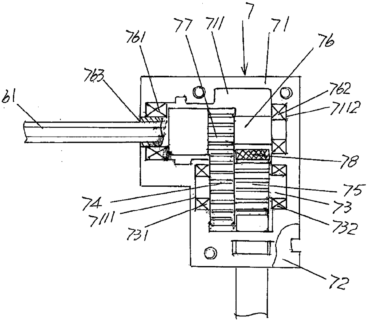
The invention provides a retracting rope device of hollow glass with built-in shutter, and belongs to the technical field of sunshade hollow glass products. The retracting rope device of hollow glasswith built-in shutter consists of a shutter blind slat turnover and a shutter blind lifting mechanism assembly, and is characterized in that the shutter blind slat and the shutter blind lifting mechanism assembly comprises a turnover shaft, a pair of rotary shaft head supporting seats and a pair of pulling rope winding rolls. The pair of rotary shaft head supporting seats is arranged in the corresponding state to each other in the using state. The pair of pulling rope winding rolls are rotationally supported on the pair of rotary shaft head supporting seats correspondingly. The middle of the turnover shaft is fixed with the pair of pulling rope winding rolls in an inserting and matched mode, but the left and right ends of the turnover shaft extend out to the pair of pulling rope winding rolls correspondingly. According to the retracting rope device of hollow glass with built-in shutter, the durable service life of a shutter blind lifting puling rope is ensured, the good lifting stationarity and easy operation are shown, the stability of a retracting rope is guaranteed, the total length of the shutter blind lifting puling rope is shortened obviously, and the probability of damage and even breakage is reduced.

Description

technical field [0001] The invention belongs to the technical field of sunshade hollow glass products, and in particular relates to a retractable and unwinding rope device for built-in blinds of hollow glass. Background technique [0002] The double-layer hollow glass built-in blinds mentioned above refer to the construction of a venetian blind that can be raised and lowered as needed in two pieces of glass (inner glass and outer glass) that are arranged in a face-to-face state and that seal the surrounding edges. A window belonging to the category of sunshade hollow glass products. This kind of window has the following self-evident advantages: good heat insulation, so as to reflect the energy saving of the building; excellent sound insulation performance, so as to avoid the noise from the outside world; Desired bright effect; by adjusting the deflection angle of the venetian blinds, it can meet the required indoor lighting requirements and protect privacy, avoiding dust an...

Claims


Application Information

Patent Timeline
Patent Type & Authority Applications(China)
IPC IPC(8): E06B9/322E06B9/326E06B9/264
CPCE06B9/264E06B9/322E06B9/326E06B2009/2643
Inventor 肖敏
Owner JIANGSU SDL ENERGY CONSERVATION TECH CO LTD
Learn More