Cap arranging device for automatic bottom cap feeding machine

A bottom cover machine and cover unscrambling technology, which is applied in the direction of conveyors, conveyor objects, transportation and packaging, etc., can solve the problem that the efficiency of equipment cover cannot be effectively improved, the efficiency of cover cannot be greatly improved, and the labor of workers is increased. Problems such as volume and labor intensity, etc., to achieve the effect of good unpacking effect, low manufacturing cost, and low solution efficiency

Active Publication Date: 2015-09-23
QUANZHOU HUASHUO IND
View PDF7 Cites 10 Cited by
  • Summary
  • Abstract
  • Description
  • Claims
  • Application Information

AI Technical Summary

Problems solved by technology

In the assembly process, both manual and mechanical equipment are used for the upper cover. Due to the low production efficiency of the manual cover and the high labor intensity of the workers, the current production line mainly adopts the automatic cover of the mechanical equipment. , but to use mechanical equipment to automatically cap, before capping, it is necessary to arrange the caps to ensure that the caps are uniformly facing upwards or downwards. Therefore, in the production process, in order to effectively ensure the bottle caps Orientation is the same, and some use manual capping, resulting in that the capping efficiency of the equipment cannot be greatly improved, and the labor intensity of workers cannot be effectively reduced; some are equipped with detection mechanisms or complex caps. The bottle caps required by the capping equipment are extracted, and then the capping equipment assembles the caps facing th

Method used


Image

  • Cap arranging device for automatic bottom cap feeding machine
  • Cap arranging device for automatic bottom cap feeding machine
  • Cap arranging device for automatic bottom cap feeding machine

Examples


Embodiment Construction

[0022] Preferred embodiments of the present invention will be described in detail below in conjunction with the accompanying drawings.

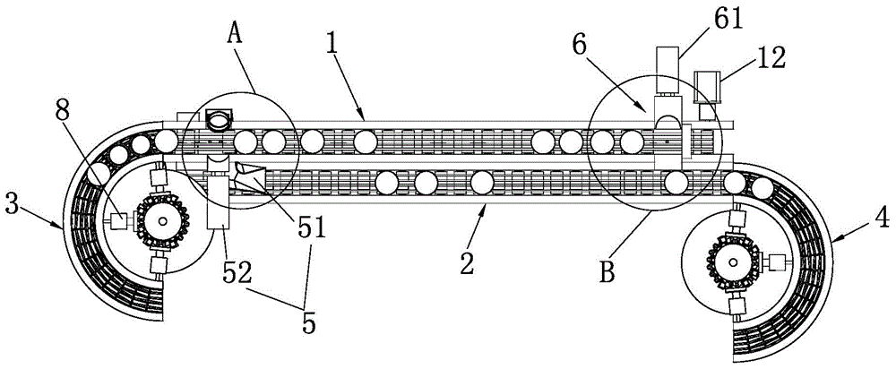
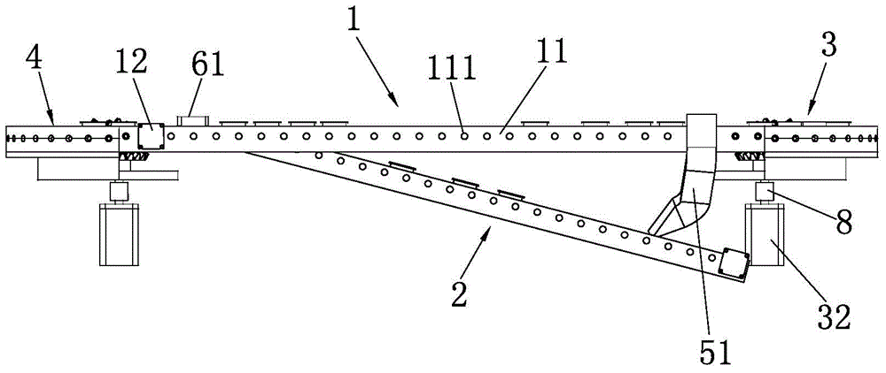
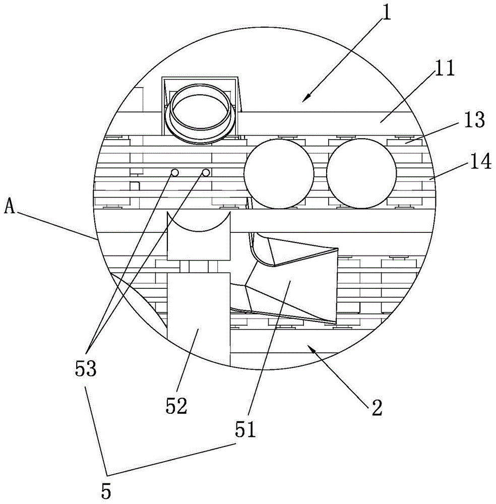
[0023] Such as Figure 1 to Figure 8 As shown, a cover sorting device for an automatic bottom cover machine includes a first feeding track 1, a second feeding track 2, a first arc-shaped delivery track 3, a second arc-shaped delivery track 4 and a control mechanism. The left and right ends of a feeding track 1 are arranged horizontally, and the second feeding track 2 is arranged on the side of the first feeding track 1 with one end low and the other end high, and the right end of the second feeding track 2 is connected with the right end of the first feeding track 1 flush with height; figure 1 As shown, the high end of the second feeding track 2 and the right end of the first feeding track 1 are arranged close to each other and a connecting groove 21 for conveying bottle caps is provided at the abutting part of the two, and the first arc-sha...


PUM


Abstract

The invention provides a cap arranging device for an automatic bottom feeding machine. The cap arranging device for the automatic bottom feeding machine comprises a first feeding track, a first arc-shaped conveying track, a second feeding track, a second arc-shaped conveying track and a control mechanism. The higher end of the second feeding track abuts against the right end of the first feeding track. The first arc-shaped conveying track is connected to the left end of the first feeding track. The second arc-shaped conveying track is connected to the end portion of the higher end of the second feeding track. The control mechanism is used for controlling operation of the cap arranging device. The cap arranging device further comprises a bottle cap turning mechanism and a bottle cap pushing mechanism. The bottle cap turning mechanism comprises a bottle cap turning groove, a first cylinder and at least two first inductors. The bottle cap pushing mechanism comprises a second cylinder, a second inductor and a blocking plate. The cap arranging device for the automatic bottom feeding machine is simple in structure, low in manufacturing cost and long in service life; production cost can be effectively reduced, and the labor intensity of workers can be effectively relieved; the cap arranging speed is high, and the cap arranging effect is good; production efficiency can be effectively improved, and the occupied space of equipment can be effectively reduced.

Description

technical field [0001] The invention relates to a cover sorting device, in particular to a cover sorting device of an automatic bottom cover loading machine. Background technique [0002] At present, bottled products in daily necessities, cosmetics and other industries are very common. For aesthetics, personalization or other packaging needs, the structural shape of the bottle body and bottle cap is also diversified, such as setting a bottom cover at the bottom of the bottle body or setting an anti-theft on the bottle body Bottle caps and the like, the bottle body and the bottle cap are generally made separately, the bottle body is placed in a centralized manner, and the bottle cap is placed in a centralized manner in addition, and then the bottle cap is assembled on the bottle body. In the assembly process, both manual and mechanical equipment are used for the upper cover. Due to the low production efficiency of the manual cover and the high labor intensity of the workers, ...

Claims


Application Information

Patent Timeline
IPC IPC(8): B65G47/256B65G21/22
Inventor 朱世钦唐宇蔡金根
Owner QUANZHOU HUASHUO IND
Why Eureka
Try Eureka