Ball push transmission device

A transmission device, sphere technology, applied in the direction of transmission device, friction transmission device, belt/chain/gear, etc., can solve the problems of unsuitable linear, circular, screw transmission applications, complex cave space terrain, unreachable and other problems , to achieve the effect of convenient replacement of wearing parts, simple structure and strong versatility

Active Publication Date: 2018-10-16
陈刚
View PDF4 Cites 0 Cited by
  • Summary
  • Abstract
  • Description
  • Claims
  • Application Information

AI Technical Summary

Problems solved by technology

Therefore, there is a need for a means of transportation that can allow passengers to ride. However, due to the complex topography of the interior space of the cave, it is not suitable for the application of conventional linear, circular, and spiral transmission technologies.
Another example is the welding of twisted bodies. The traditional welding manipulator will have dead angles that cannot be reached. Therefore, it is necessary to provide a technology that can continuously move the clamping welding tongs at various angles.

Method used


Image

  • Ball push transmission device
  • Ball push transmission device
  • Ball push transmission device

Examples


Embodiment Construction

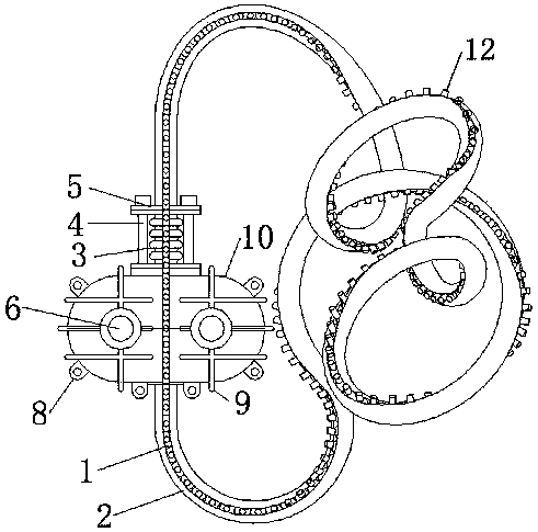
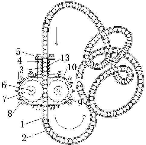
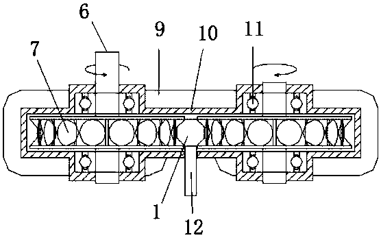
[0018] Such as figure 1 , figure 2 As shown, a push ball transmission device of the present invention includes a ball 1, an open pipe 2, a bellows expansion joint 3, a casing 4, a shaft 6, a ball wheel 7, a casing 10, a bearing 11, and a ball handle 12 , Socket expansion tube 13. The open pipe 2 is a fixed serpentine curve; one end of the open pipe 2 is connected to one end of the bellows expansion joint 3, the other end of the open pipe 2 is connected to one end of the shell 10, and the other end of the bellows expansion joint 3 is connected to the other end of the shell 10; the ball 1 It is a whole connected with the ball handle 12 , the ball 1 is located in the open pipe 2 , and the ball handle 12 is located at the opening of the open pipe 2 .

[0019] Such as figure 2 , Figure 4 As shown, the open pipe 2 and the bellows telescopic joint 3 are connected by a flange 5, the open pipe 2 and the casing 4 are connected by a circlip, and the bellows telescopic joint 3 plac...


PUM


Abstract

The invention provides a ball push transmission device, and belongs to the field of mechanical transmission devices. The ball push transmission device comprises balls, an open pipeline, a corrugated pipe expansion joint, a machine shell, shaft rods, ball gap wheels, a shell, bearings, ball handles and a socket and spigot expansion pipe. The open pipeline is in a fixed S-shaped curve and is connected with the corrugated pipe expansion joint and the shell. The balls and the ball handles are combined into a whole, and the balls are arranged in the open pipeline. A gap with the size equal to the size of each ball is reserved between the two ball gap wheels. When the ball gap wheels rotate, each ball can be pushed into the open pipeline, each poked ball pushes the other ball, the balls drive the ball handles, and therefore running of the ball handles is achieved. The ball push transmission device has the advantages that the structure is simple, the universality is high, and various series of products and various styles of ball handles can be designed. Multi-mode combination is conducted through the combination of the task content in the purchasing process, and the requirements of different working conditions are met. The storage and release performance, the coordination performance, the stability and the maintainability are good.

Description

technical field [0001] The invention relates to the field of mechanical transmission devices, in particular to a ball pushing transmission device. Background technique [0002] Most of the current transmission devices are simple in direction and have the same interface. Sometimes we also need a transmission device that can complete complex directions, different interfaces, twists, and prescribed lines. For example, when visiting karst cave attractions, because tourists can only walk, physical exhaustion will occur. Therefore, there is a need for a means of transportation that can allow passengers to ride. However, due to the complex terrain inside the cave, it is not suitable for the application of conventional linear, circular, and spiral transmission technologies. Another example is the welding of twisted bodies. The traditional welding manipulator will have dead angles that cannot be reached. Therefore, it is necessary to provide a technology that can continuously move ...

Claims


Application Information

Patent Timeline
Patent Type & Authority Applications(China)
IPC IPC(8): F16H13/04
CPCF16H13/04
Inventor 陈刚
Owner 陈刚
Why Eureka
Try Eureka