Energy-saving optimization control system and method for end equipment of central air conditioning system

A central air-conditioning system and terminal equipment technology, applied in the direction of control input related to air characteristics, space heating and ventilation control input, mechanical equipment, etc. Temperature difference and other problems, to achieve the effect of reducing fan energy consumption, improving stability, and small overshoot

Active Publication Date: 2018-10-16
GUANGZHOU UNIVERSITY
View PDF4 Cites 19 Cited by
  • Summary
  • Abstract
  • Description
  • Claims
  • Application Information

AI Technical Summary

Problems solved by technology

And as the indoor load continues to decrease, the flow rate will decrease, and the temperature of the outlet water will rise very high, which is far from the designed temperature difference between the inlet and outlet water.
In the control process of the terminal equipment, if only the chilled water flow is adjusted, on the one hand, the temperature difference between the inlet and outlet water of the terminal equipment will deviate from the design value (such as 5°C), because generally when the chilled water flow rate is 40% of the design value, the surface heat transfer The heat exchange of the device has reached about 70% of the rated heat exchange, so at partial load, if the chilled water flow is only changed to adapt to the load change, the chilled water flow will be greatly reduced, which will affect the indoor dehumidification

Method used


Image

  • Energy-saving optimization control system and method for end equipment of central air conditioning system
  • Energy-saving optimization control system and method for end equipment of central air conditioning system
  • Energy-saving optimization control system and method for end equipment of central air conditioning system

Examples


Embodiment 1

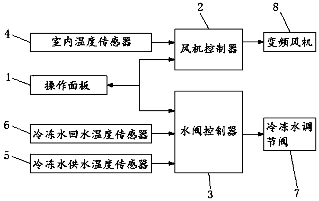
[0037] Embodiment 1 of the present invention provides an energy-saving optimization control system for terminal equipment of a central air-conditioning system, such as figure 1 As shown, it includes operation panel 1, fan controller 2, water valve controller 3, indoor temperature sensor 4, chilled water supply temperature sensor 5, chilled water return temperature sensor 6, chilled water regulating valve 7 and frequency conversion fan 8, and the fan Both the controller 2 and the water valve controller 3 are provided with a PID calculation module inside;

[0038] The operation panel 1 is connected to the signal input end of the fan controller 2 and the water valve controller 3, the indoor temperature sensor 4 is connected to the signal input end of the fan controller 2, the frequency conversion fan 8 is connected to the signal output end of the fan controller 2, and the chilled water is supplied Both the temperature sensor 5 and the chilled water return temperature sensor 6 are...


PUM


Abstract

The invention provides an energy-saving optimization control system and method for end equipment of a central air conditioning system. The method comprises the steps that the set room temperature andthe set temperature difference between supply water and return water of chilled water are input into an operation panel; the temperature of an air conditioned room, the supply water temperature and the return water temperature of the chilled water are detected in real time by all sensors, the signal of the temperature of the air conditioned room is output to a fan controller, and the signals of the supply water temperature and the return water temperature of the chilled water are output to a water valve controller; and the temperature deviation of the room and the temperature difference deviation of the supply water and the return water of the chilled water are calculated; and the temperature deviation of the room or the temperature difference deviation of the supply water and the return water of the chilled water are judged, and the rotating speed of a fan or the opening degree of a water valve is controlled according to the judgment result. According to the method, the return air temperature, the supply water temperature and the return water temperature are continuously acquired, after PID algorithm operational treatment, the air speed of an air blower and the opening degree of asurface cooler chilled water adjusting valve are adjusted, the indoor temperature and the temperature difference between the supply water and the return water of the chilled water can be stabilized at set values, and therefore the comfort of the system can be improved.

Description

technical field [0001] The invention belongs to the technical field of central air-conditioning terminal equipment, and in particular relates to an energy-saving optimization control system and method for central air-conditioning system terminal equipment. Background technique [0002] According to relevant data, the energy consumption of the terminal equipment accounts for 25% to 35% of the energy consumption of the central air-conditioning system. Effectively reducing the energy consumption of the terminal equipment is an important part of reducing the energy consumption of the central air-conditioning system. When designing air-conditioning projects, the terminal load is calculated according to the maximum value. When selecting equipment, the calculated load or calculated flow is used as a reference. Generally, a certain margin is also considered, so the equipment will be oversized. In actual operation, the central air-conditioning system operates at 65% of the maximum lo...

Claims


Application Information

Patent Timeline
Patent Type & Authority Applications(China)
IPC IPC(8): F24F11/89F24F11/77F24F11/64F24F110/10
CPCF24F11/64F24F11/77F24F11/89F24F2110/10Y02B30/70
Inventor 徐晓宁苏千劲方赵嵩丁云飞
Owner GUANGZHOU UNIVERSITY
Why Eureka
Try Eureka