
Bias Current Generation Circuit

A technology for generating circuits and bias currents. It is applied in the direction of adjusting electrical variables, instruments, and control/regulating systems. It can solve the problem that the bias current output is not related to the control current, and achieve simple structure, high circuit reliability, and high circuit reliability. The effect of the small size of the board

Active Publication Date: 2020-05-01
SEMICON MFG INT (SHANGHAI) CORP +1
View PDF5 Cites 0 Cited by
  • Summary
  • Abstract
  • Description
  • Claims
  • Application Information

AI Technical Summary

Problems solved by technology

[0005] The purpose of the present invention is to provide a bias current generating circuit to solve the problem that the output of the additional bias current and the control current of the existing bias current generating circuit are not related

Method used


Image

  • Bias Current Generation Circuit
  • Bias Current Generation Circuit

Examples


Embodiment Construction

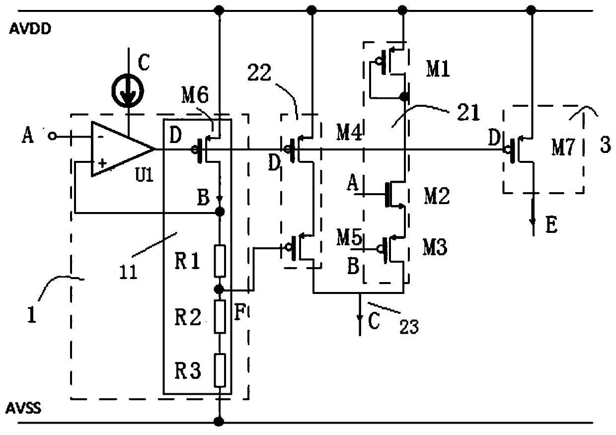
[0041] The bias current generation circuit proposed by the present invention will be further described in detail below in conjunction with the accompanying drawings and specific embodiments. Advantages and features of the present invention will be apparent from the following description and claims. It should be noted that all the drawings are in a very simplified form and use imprecise scales, and are only used to facilitate and clearly assist the purpose of illustrating the embodiments of the present invention.

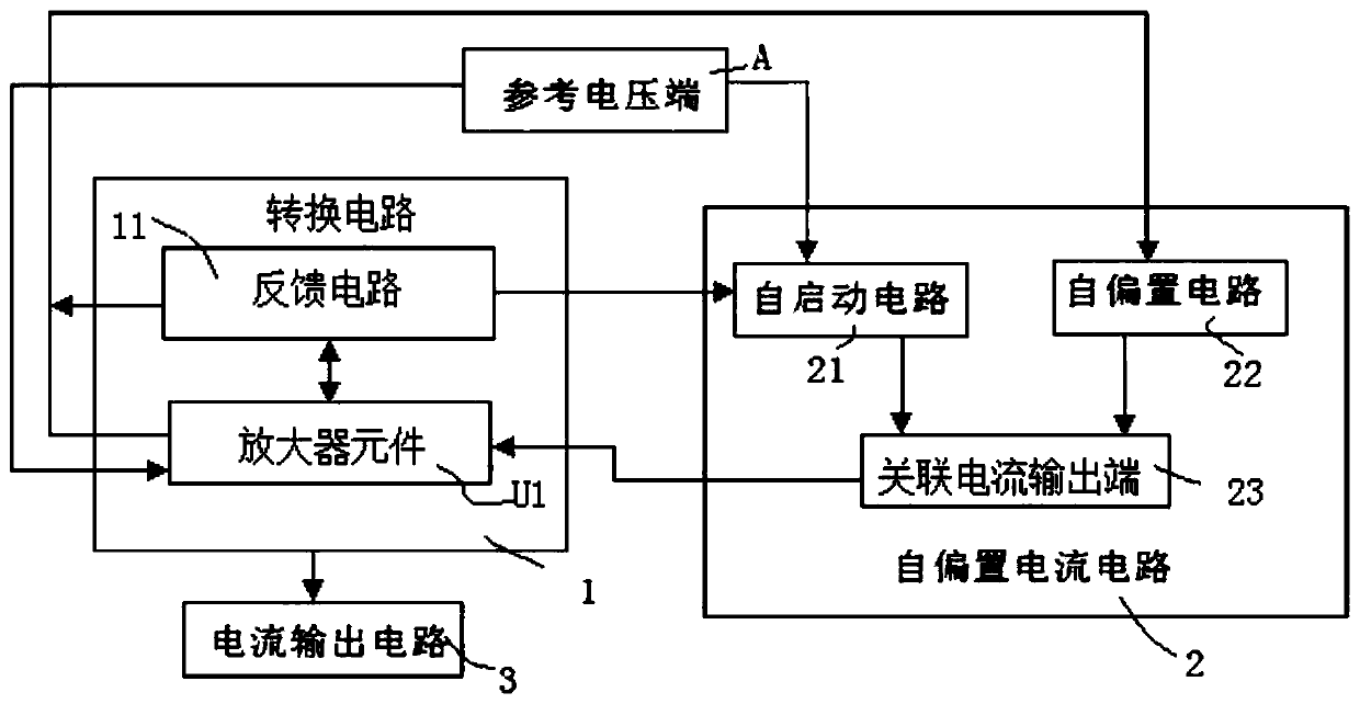
[0042] The core idea of ​​the present invention is to provide a bias current generating circuit to solve the problem that the output of the extra bias current required by the existing bias current generating circuit is not related to the control current.

[0043] In order to realize the above ideas, the present invention provides a bias current generating circuit, the bias current generating circuit includes a reference voltage terminal, a conversion circuit, a self-...


PUM


Abstract

The invention provides a bias current generating circuit which comprises a reference voltage end, a switching circuit, a self-bias current circuit and a current output circuit, wherein the reference voltage end supplies reference voltage to the switching circuit and the self-bias current circuit; the self-bias current circuit forms first association current according to the reference voltage, andthe first association current is supplied to the switching circuit; the switching circuit comprises an amplifier component, starting of the amplifier component is controlled by the first association current, and the amplifier component generates control current according to the reference voltage, and the control current is supplied to the self-bias current circuit and the current output circuit; the self-bias current circuit generates second association current according to the control current, and operation of the amplifier component is controlled by the second association current after beingstarted; the current output circuit outputs bias current according to the control current.

Description

technical field [0001] The invention relates to the technical field of semiconductors, in particular to a bias current generating circuit. Background technique [0002] The traditional bias current generating circuit provides bias current for the amplifier circuit, but because its internal structure also has amplifier components, and the traditional bias current generating circuit cannot provide bias current by itself, so an additional circuit structure is required, and the additional The circuit structure needs to increase the circuit board area and power consumption, and because the output of the extra current generated is not related to the bias current of the final output, if the extra current generated is too large, it will affect the stability of the circuit and make the amplifier components offset voltage Increase, affect the accuracy of the amplifier components, if the additional current is too small, the bias current generation circuit will not work properly. [00...

Claims


Application Information

Patent Timeline
Patent Type & Authority Patents(China)
IPC IPC(8): G05F1/56
CPCG05F1/561
Inventor 陈廷乾
Owner SEMICON MFG INT (SHANGHAI) CORP
Learn More