Method for designing a die surface

A mold surface and model technology, applied in the field of computer program products, can solve the problems of high-tech engineers' needs, limitations, inability to fully explain metals, and difficulty in predicting

Active Publication Date: 2018-10-16
HEXAGON TECH CENT GMBH
View PDF6 Cites 0 Cited by
  • Summary
  • Abstract
  • Description
  • Claims
  • Application Information

AI Technical Summary

Problems solved by technology

The need for highly skilled engineers is also a limiting factor as it takes years of experience to become an expert in the process
[0012] Using FE analysis to help design die faces has improved initial die face quality, but does not fully account for the behavior of the metal (since the metal deforms as the die closes)
The behavior of newer materials such as high strength steel and aluminum is even less predictable and leads to substantially longer time periods for repeating to acceptable quality

Method used


Image

  • Method for designing a die surface
  • Method for designing a die surface
  • Method for designing a die surface

Examples


Embodiment Construction

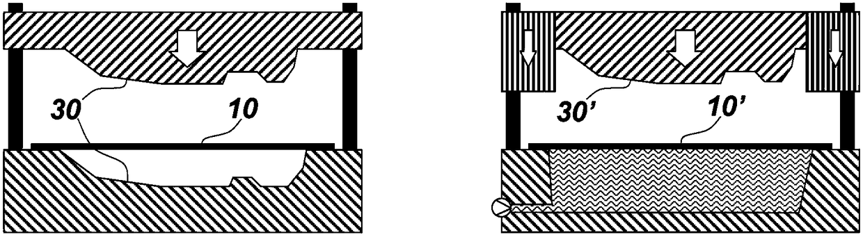
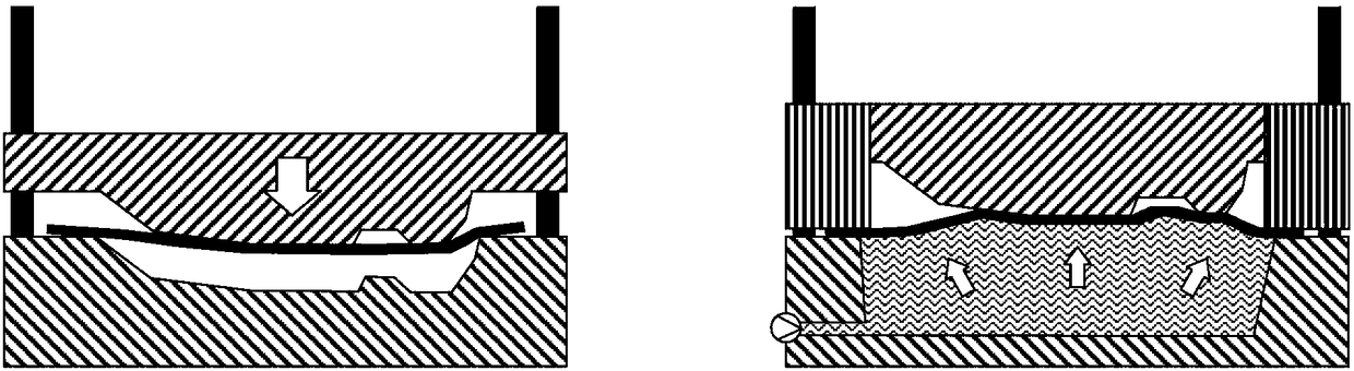
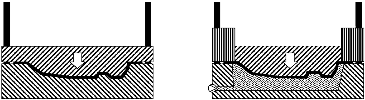
[0055] Figure 1a to Figure 1d Two exemplary manufacturing processes are shown for forming workpieces 10 / 10' into actual formed parts 20 / 20'. In the embodiment on the left, which abstractly shows a conventional punch, the die includes a die face 30 . In the embodiment on the right, abstractly showing a fluid forming machine, the mold includes a mold face 30'. However, the present invention is also compatible with other manufacturing processes as long as they involve forming and include a mold with a mold surface intended to form a workpiece into a part.

[0056] as in Figure 1d In both cases, the residual stresses due to the forming process cause springback in the part 20 / 20' when it is actually formed when it is released from the die face. Residual stress is mainly responsible for the deviation of the part from the die surface. In particular, the present invention provides a more accurate prediction of such springback. This prediction allows the die face to be ...


PUM


Abstract

The invention relates to a method for designing a die surface of a die, comprising generating a workpiece simulation-model corresponding to a workpiece, generating a target simulation-model corresponding to a target formed part, determining an initial die surface, which an initial numerical simulation predicts as forming the workpiece simulation-model into the target simulation-model, determiningresidual stresses resulting from forming the workpiece simulation-model into the target simulation-model, with a die having the initial die surface, forming the workpiece into an actual formed part, by measuring the actual formed part, generating a numerical representation of the actual formed part, based on the numerical representation of the actual formed part, generating an actual simulation-model, based on the residual stresses, matching the actual simulation-model and the target simulation-model, based on deviations between the matched target simulation-model and actual simulation-model,modifying the initial numerical simulation to provide a modified numerical simulation, and determining a corrected die surface, which the modified numerical simulation predicts as forming the workpiece simulation-model into the target simulation-model.

Description

technical field [0001] The present invention relates to a method according to claim 1 and a computer program product according to claim 12 . Background technique [0002] Much of the fabrication involves producing complex shapes from sheet metal and then joining these parts together to form structures. These individual shapes are primarily produced by a process known as stamping. During the stamping process, a flat sheet of metal is placed in a die set, usually consisting of a male and female tool that, when closed together under pressure, forms the sheet of metal to the desired shape. The die faces are designed using computer aided design (CAD) software and then machined into tool steel to make the mold. [0003] The initial process of creating a die face typically involves using finite element analysis (FEA) software to predict how the metal will deform when the die is closed. The deformation includes effects like stretching, wrinkling, and springback. [0004] Spring...

Claims


Application Information

Patent Timeline
IPC IPC(8): G06F17/50
CPCG06F30/23G06F2119/06B21D22/00B21D37/20G06F2113/24G06F2119/18G06F2111/10G06F30/17Y02P90/02G06F30/20G06N5/04
Inventor W·威尔科克斯D·皮玲
Owner HEXAGON TECH CENT GMBH
Why Eureka
Try Eureka