
Stable sliding potentiometer

A type of sliding, potentiometer technology, applied in the field of potentiometers, can solve the problems of affecting the use effect, the inaccurate adjustment of the brush and the resistance sheet, and the offset on both sides of the lever, so as to achieve the effect of convenient assembly and processing.

Pending Publication Date: 2018-10-16
东莞福哥电子有限公司
View PDF0 Cites 2 Cited by
  • Summary
  • Abstract
  • Description
  • Claims
  • Application Information

AI Technical Summary

Problems solved by technology

For the convenience of assembly, in the prior art, the width of the sliding seat is usually set slightly larger than the width of the brush. When the lever is moved, the lever tends to shift to both sides, and the lever shifts when it is moved. It will affect the user's feel, which will lead to the inaccurate adjustment of the brush and the resistance sheet. When it is used in fields with high precision requirements such as medical treatment, it will seriously affect the use effect. The existing sliding potentiometer is not suitable for fine adjustment.

Method used


Image

  • Stable sliding potentiometer
  • Stable sliding potentiometer
  • Stable sliding potentiometer

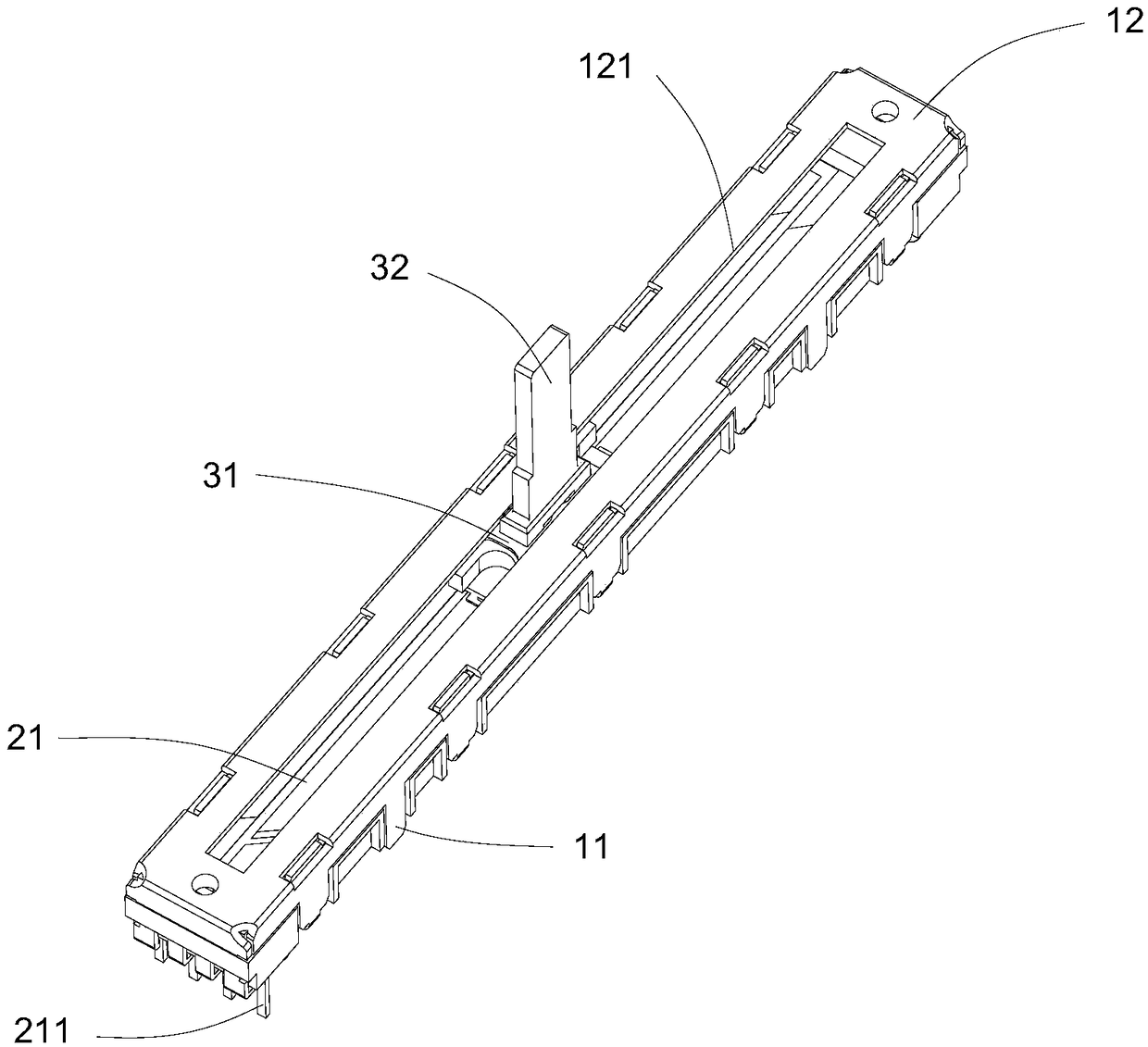
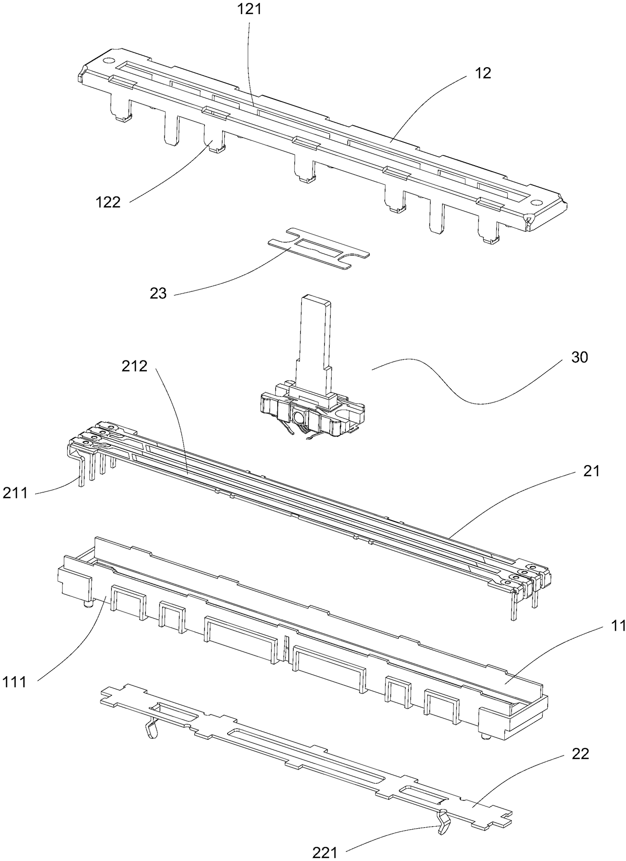
Examples


Embodiment Construction

[0022] In order to further understand the features, technical means, and specific objectives and functions achieved by the present invention, the present invention will be further described in detail below in conjunction with the accompanying drawings and specific embodiments.

[0023] refer to Figure 1 to Figure 3 .

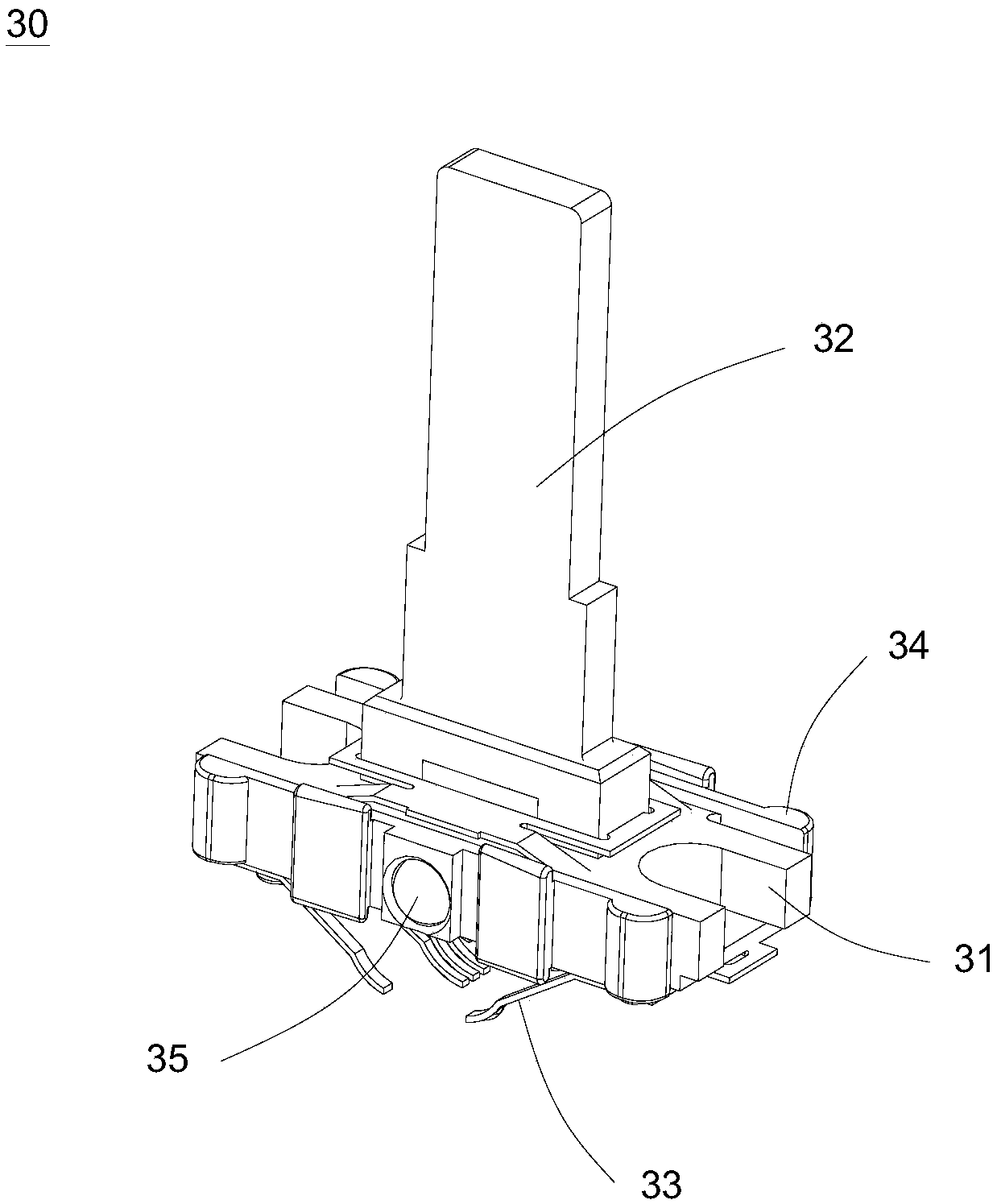
[0024] The embodiment of the present invention discloses a stable sliding potentiometer, which is characterized in that it includes a sliding seat 11, an upper cover 12 is connected to the sliding seat 11, a resistance sheet 21 is fixed inside the sliding seat 11, and a sliding block is connected to the resistance sheet 21. The brush mechanism 30, the resistance sheet 21 and the sliding brush mechanism 30 are arranged between the sliding seat 11 and the upper cover 12;

[0025] The upper cover 12 is provided with a relief groove 121;

[0026] Both ends of the resistance sheet 21 are provided with a plurality of terminals 211, the terminals 211 are arranged th...


PUM


Abstract

The invention provides a stable sliding potentiometer. The stable sliding potentiometer is characterized by comprising a sliding seat, wherein the sliding seat is connected with an upper cover; a resistor chip is fixed in the sliding seat and connected with a sliding brush mechanism; a plurality of conduction tracks are arranged on the resistor chip; the sliding brush mechanism comprises a slidingblock; a driving lever is fixed on the sliding block; the bottom of the sliding block is connected with a plurality of contact pins; the contact pins are in sliding connection with the conduction tracks; sliding spring plates are arranged at two sides of the sliding block; the head ends of the sliding spring plates are fixedly connected with the sliding block; a space is arranged between the tailend of each sliding spring plate and the sliding block; and the tail ends of the sliding spring plates are in contact with an inner wall of the sliding seat. According to the stable sliding potentiometer, the position between the sliding block and the sliding seat can be effectively limited, so that the sliding block is effectively prevented from deflecting when the driving lever is stirred, a stable adjustment basis can be provided for a user, the user can complete fine-tuning operations with high accuracy requirements through stirring the driving lever and the stable sliding potentiometer can be applied to the fields, such as medical treatment, with high accuracy requirements.

Description

technical field [0001] The invention relates to a potentiometer, and in particular discloses a stable sliding potentiometer. Background technique [0002] The potentiometer is a resistive element with three leads and the resistance value can be adjusted according to a certain change rule. The potentiometer is usually composed of a resistor body and a movable brush. When the brush moves along the resistor body, the output terminal is obtained. The resistance value or voltage that has a certain relationship with the displacement. The potentiometer can be used as a three-terminal element or as a two-terminal element. The latter can be regarded as a variable resistor. Since its function in the circuit is to obtain an output voltage that has a certain relationship with the input voltage, it is called It is a potentiometer. [0003] The sliding potentiometer, also known as the straight sliding potentiometer, is that the brush slides along the linear resistance piece on the slidi...

Claims


Application Information

Patent Timeline
Patent Type & Authority Applications(China)
IPC IPC(8): H01C10/38H01C1/022H01C1/12
CPCH01C1/022H01C1/12H01C10/38
Inventor 刘晟睿
Owner 东莞福哥电子有限公司
Learn More