
Isolation switch circuit and control method thereof

A switch circuit and isolated technology, applied in the field of isolated switch circuit and its control, can solve the problems of high cost and low precision, achieve the effect of precise control and adjustment, and reduce circuit cost

Active Publication Date: 2018-10-16
JOULWATT TECH INC LTD
View PDF4 Cites 12 Cited by
  • Summary
  • Abstract
  • Description
  • Claims
  • Application Information

AI Technical Summary

Problems solved by technology

[0004] The purpose of the present invention is to provide an isolated switch circuit and its control method, which solves the technical problems of high cost and low precision in the prior art, so as to improve the detection precision of the feedback signal and facilitate the realization of control with high precision

Method used


Image

  • Isolation switch circuit and control method thereof
  • Isolation switch circuit and control method thereof
  • Isolation switch circuit and control method thereof

Examples


Embodiment Construction

[0036] Preferred embodiments of the present invention will be described in detail below with reference to the accompanying drawings, but the present invention is not limited to these embodiments. The present invention covers any alternatives, modifications, equivalent methods and schemes made within the spirit and scope of the present invention.

[0037] In order to provide the public with a thorough understanding of the present invention, specific details are set forth in the following preferred embodiments of the present invention, but those skilled in the art can fully understand the present invention without the description of these details.

[0038] In the following paragraphs the invention is described more specifically by way of example with reference to the accompanying drawings. It should be noted that all the drawings are in simplified form and use inaccurate scales, which are only used to facilitate and clearly assist the purpose of illustrating the embodiments of the...


PUM


Abstract

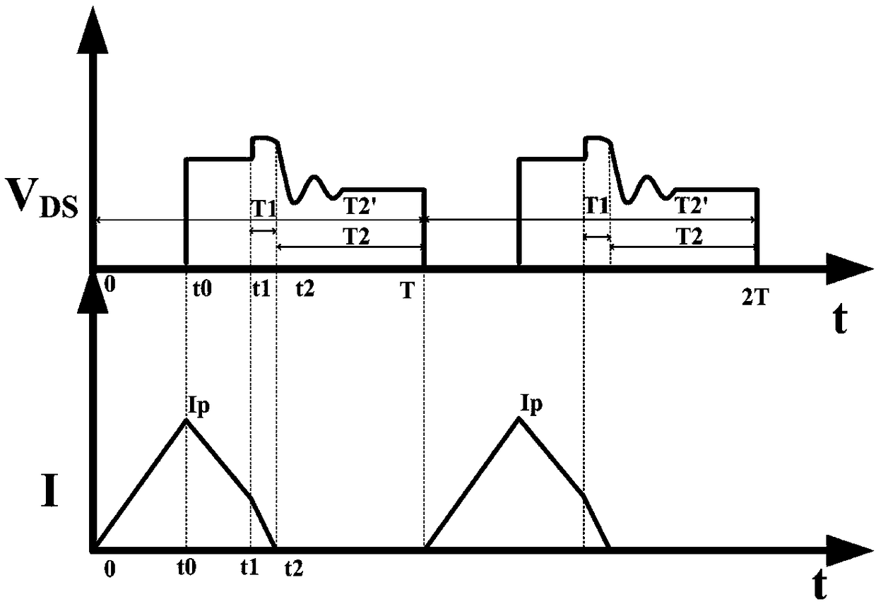
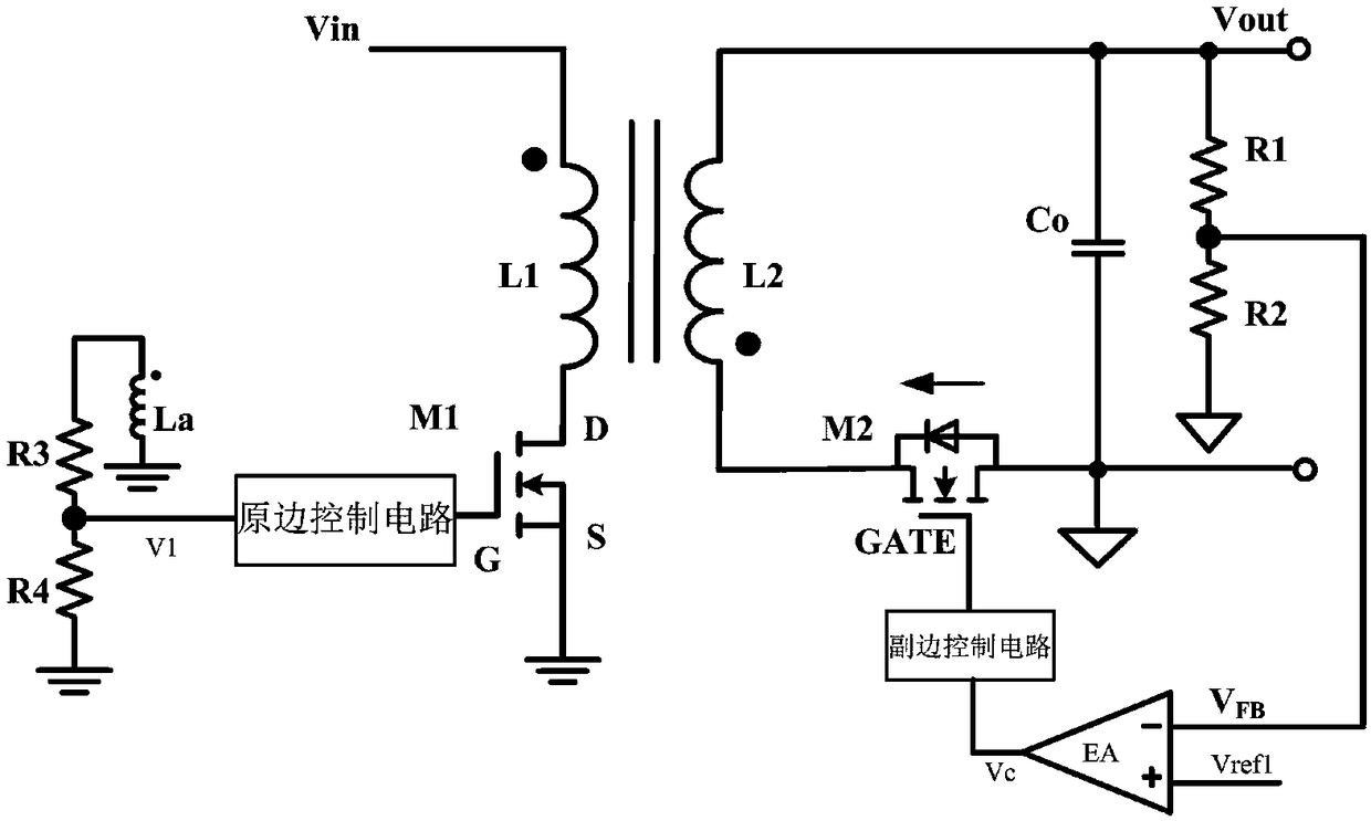
The invention discloses an isolation switch circuit and a control method thereof. Control and adjustment of a primary edge and a secondary side are performed by first time information as characteristic, a photocoupler is not needed to transmit information of the primary edge and the secondary side, the primary edge is used for identifying first time by detecting voltages of two ends of a main power switch tube, the secondary edge is used for obtaining a first control signal representing information of the first time by sampling an output voltage or / and an output current and comparing with a corresponding reference signal, the primary edge can be used for adjusting second time and a peak current according to the information of the first time, the first control signal is higher than a thirdthreshold, the isolation switch circuit works at a fixed frequency, and the isolation switch circuit enters a continuous conduction mode or an interrupted conduction mode under the fixed frequency. The photocoupler is not needed to perform signal isolation and transmission of the primary edge and the secondary edge, the circuit cost is reduced, the freewheeling time of a parasitic diode of a synchronous rectification tube is used as the characteristic for identification and control, and control and adjustment are more accurate.

Description

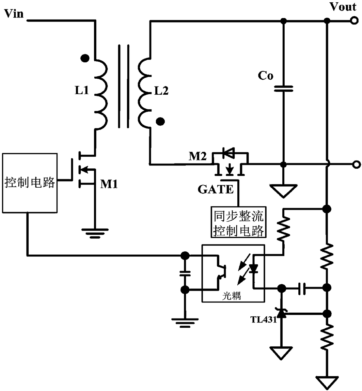
technical field [0001] The invention relates to the technical field of power electronics, in particular to an isolated switch circuit and a control method thereof. Background technique [0002] Synchronous rectification is a method of replacing rectifier diodes with power MOSFETs with lower on-state resistance to reduce rectification losses, and is used in isolated switching circuits. The isolated switch circuit in the prior art generally includes a main power switch tube, a transformer and a synchronous rectifier tube, the conduction state of the main power switch tube is controlled by the control circuit, and the synchronous rectifier tube is controlled by the synchronous rectification control circuit to realize synchronous rectification. In isolated switching circuits, optocouplers are often used to transmit feedback signals from the primary and secondary sides. [0003] Such as figure 1 As shown in FIG. 1 , it illustrates the prior art flyback switching circuit based o...

Claims


Application Information

Patent Timeline
Patent Type & Authority Applications(China)
IPC IPC(8): H02M3/335
CPCH02M3/33592Y02B70/10
Inventor 黄必亮任远程周逊伟
Owner JOULWATT TECH INC LTD
Learn More