
Cutting device for machinery manufacturing and cutting method

A technology of machinery manufacturing and cutting device, applied in the field of cutting device for machinery manufacturing, can solve the problems of inconvenient and disadvantageous operation, reduce the production cost of enterprises, etc., and achieve the effect of reducing production cost, improving convenience and enhancing practicability

Pending Publication Date: 2018-10-19
盐城市诚益通机械制造有限责任公司
View PDF4 Cites 2 Cited by
  • Summary
  • Abstract
  • Description
  • Claims
  • Application Information

AI Technical Summary

Problems solved by technology

[0004] The purpose of the present invention is to provide a cutting device and a cutting method for mechanical manufacturing to solve the problem that the existing aluminum plate cutting device proposed in the above background technology has a complex structure, inconvenient operation, and cannot conveniently adjust the positions of multiple blades, and There is no function of recycling the waste generated by cutting, which is not conducive to reducing the production cost of the enterprise

Method used


Image

  • Cutting device for machinery manufacturing and cutting method
  • Cutting device for machinery manufacturing and cutting method
  • Cutting device for machinery manufacturing and cutting method

Examples


Embodiment Construction

[0023] The following will clearly and completely describe the technical solutions in the embodiments of the present invention with reference to the accompanying drawings in the embodiments of the present invention. Obviously, the described embodiments are only some, not all, embodiments of the present invention. Based on the embodiments of the present invention, all other embodiments obtained by persons of ordinary skill in the art without making creative efforts belong to the protection scope of the present invention.

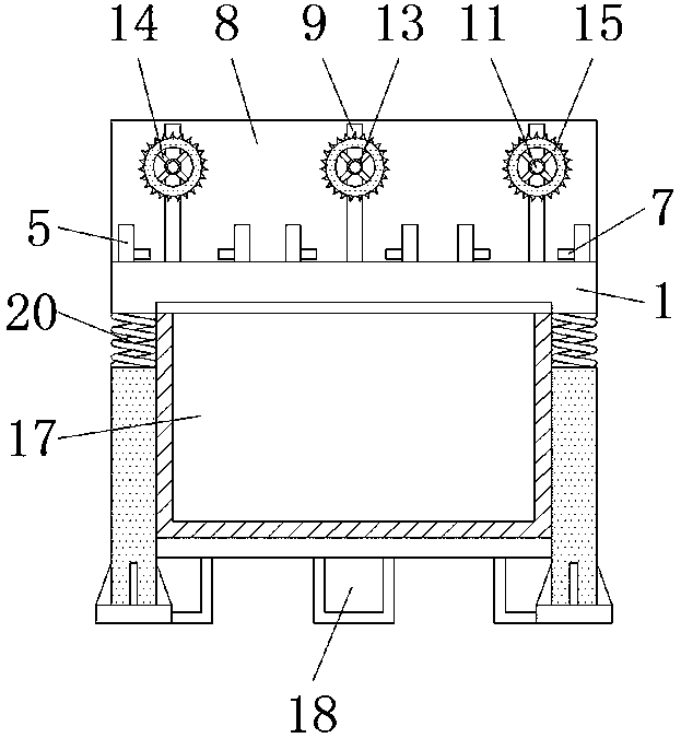
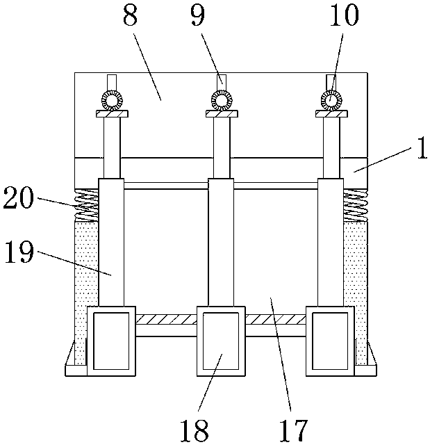
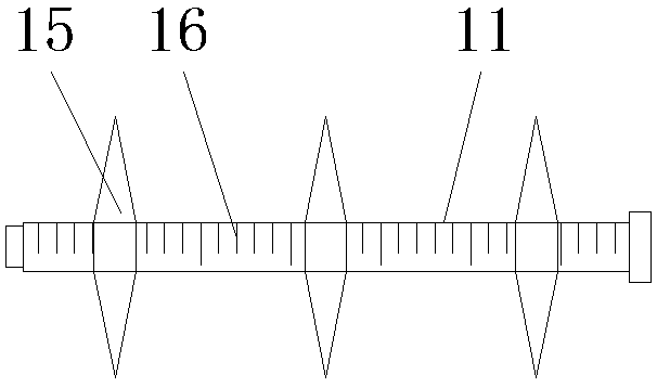
[0024] see Figure 1-7 , the present invention provides a technical solution: a cutting device for mechanical manufacturing, including a cutting table 1, a steel plate 2, a strip-shaped through hole 3, a chute 4, a slider 5, a return spring 6, a pressing block 7, a support plate 8. Empty slot 9, motor 10, rotating shaft 11, threaded hole 12, fixed ring 13, connecting rod 14, cutting blade 15, scale line 16, debris box 17, oil cylinder 18, hydraulic rod 19 and ...


PUM


Abstract

The invention discloses a cutting device for machinery manufacturing and a cutting method. The cutting device comprises a cutting table, a support plate and vibration reduction springs, wherein a steel plate is arranged on the cutting table; strip-shaped through holes are formed in the steel plate; a slide groove is formed in the front side of the strip-shaped through holes; slide blocks are arranged on the slide groove; a return spring is arranged inside each slide block; a compression block is connected under each return spring; the support plate is positioned above the cutting table; hollowgrooves are formed in the support plate; a motor is arranged at the back side of each hollow groove; the front end of each motor is connected with a rotating shaft; threaded holes are formed in the rotating shaft; and a fixing ring is arranged at the outer side of the threaded hole. Scale lines, the threaded holes and the fixing rings are arranged on the cutting device for machinery manufacturing; the space between cutting blades can be conveniently regulated so as to adapt to the cutting dimension required by different plates; the structure is simple; workers can conveniently perform practical operation; and the convenience of the device is improved.

Description

technical field [0001] The invention relates to the technical field related to mechanical manufacturing, in particular to a cutting device and a cutting method for mechanical manufacturing. Background technique [0002] In the machinery manufacturing industry, various processing procedures are required, and the cutting step is one of the most common mechanical processing steps. Due to its excellent characteristics, aluminum metal is widely used in the machinery manufacturing industry, but now Some aluminum plate cutting devices have complex structure, inconvenient operation, cannot conveniently adjust the positions of multiple blades, and do not have the function of recycling the waste generated by cutting, which is not conducive to reducing the production cost of the enterprise. [0003] In view of the above problems, an innovative design is carried out on the basis of the original cutting device. Contents of the invention [0004] The purpose of the present invention is...

Claims


Application Information

Patent Timeline
Patent Type & Authority Applications(China)
IPC IPC(8): B23Q11/00B23Q17/22B23Q3/06B23D47/10
CPCB23D47/10B23Q3/06B23Q3/062B23Q11/00B23Q11/0042B23Q17/22Y02P70/10
Inventor 张大军张洁凡张金斌
Owner 盐城市诚益通机械制造有限责任公司
Learn More