Building material stacking frame

A technology for building materials and stacking racks, applied in the field of construction equipment, which can solve problems such as single fixed structure, no spacing adjustment structure, and inability to stack tubular building materials, etc., and achieve good waterproof effect, flexible use, and convenient operation.

Inactive Publication Date: 2018-10-19
黄鑫
View PDF0 Cites 3 Cited by
  • Summary
  • Abstract
  • Description
  • Claims
  • Application Information

AI Technical Summary

Problems solved by technology

[0002] The building material stacking rack is a kind of shelf that plays a role of storing and placing building materials. Through the building material stacking rack, different types of building materials can be placed at the same time, which reduces the space occupied by building materials and plays a better role in storing and sorting; the existing There are certain disadvantages in the use of advanced building material stacking racks. The fixed structure of traditional building material stacking racks is relatively simple, and tubular building materials cannot be stacked, which makes tubular building materials prone to scattering during the stacking process. The top of traditional building material stacking racks does not have protection. structure, it is impossible to protect the building materials in rainy days. The traditional building material stacking rack does not have a spacing adjustment structure, and the upper and lower spacing of the building material stacking rack cannot be adjusted according to the size and type of building materials, which has brought a certain impact on users. For this reason, We propose a stacking rack for building materials

Method used


Image

  • Building material stacking frame
  • Building material stacking frame
  • Building material stacking frame

Examples


Embodiment Construction

[0017] In order to make the technical means, creative features, goals and effects achieved by the present invention easy to understand, the present invention will be further described below in conjunction with specific embodiments.

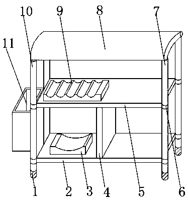
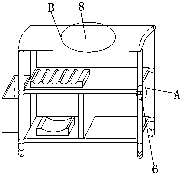
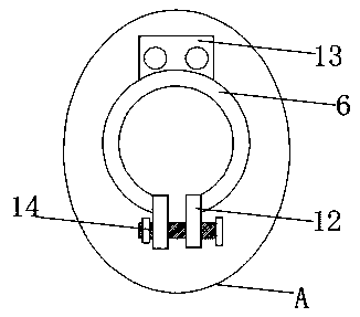
[0018] Such as Figure 1-4 As shown, a kind of building materials stacking rack comprises No. 1 storage board 2 and No. 2 storage board 5, the upper end outer surface of No. 1 storage board 2 is fixedly installed with partition plate 4, and the upper end outer surface of No. 1 storage board 2 A fixed bucket seat 3 is fixedly installed on one side close to the partition plate 4, a No. 2 support rod 10 is fixedly installed on one side of the No. 1 storage board 2, and a No. support rod 7, No. 2 support rod 10 and the outer surface of the lower end of No. 1 support rod 7 are all fixedly installed with shock-absorbing pad 1, No. 2 storage board 5 is fixedly installed on the top of No. 1 storage board 2, and No. 2 storage board The outer surface of th...


PUM


Abstract

The invention discloses a building material stacking frame. The building material stacking frame comprises a first object placing plate and a second object placing plate, a partition plate is fixedlyinstalled on the outer surface of the upper end of the first object placing plate, and a fixed barrel seat is fixedly installed on one side, close to the partition plate, of the outer surface of theupper end of the first object placing plate; a second supporting rod is fixedly installed on the outer surface of one side of the first object placing plate, and a first supporting rod is fixedly installed on the outer surface of the other side of the first object placing plate; and damping foot pads are fixedly installed on the outer surface of the lower end of the second supporting rod and the outer surface of the lower end of the first supporting rod correspondingly, and the second object placing plate is fixedly installed above the first material placing plate, and a pipe fixing seat is fixedly installed on the outer surface of the upper end of the second object placing plate. According to the building material stacking frame, a protection cover plate, the pipe fixing seat and a lifting pipe sleeve are arranged, the stacking frame is enabled to be provided with a waterproof structure, the height of the stacking frame can be adjusted, so that a tubular building material can be placed more firmly, and a better application prospect is brought.

Description

technical field [0001] The invention relates to the field of construction equipment, in particular to a stacking rack for building materials. Background technique [0002] The building material stacking rack is a kind of shelf that plays a role of storing and placing building materials. Through the building material stacking rack, different types of building materials can be placed at the same time, which reduces the space occupied by building materials and plays a better role in storing and sorting; the existing There are certain disadvantages in the use of advanced building material stacking racks. The fixed structure of traditional building material stacking racks is relatively simple, and tubular building materials cannot be stacked, which makes tubular building materials prone to scattering during the stacking process. The top of traditional building material stacking racks does not have protection. structure, it is impossible to protect the building materials in rainy ...

Claims


Application Information

Patent Timeline
Patent Type & Authority Applications(China)
IPC IPC(8): B25H3/04
CPCB25H3/04
Inventor 黄鑫
Owner 黄鑫
Why Eureka
Try Eureka