
Hydraulic cylinder with gap dynamic sealing piston

A dynamic sealing and hydraulic cylinder technology, applied in the field of hydraulic cylinders, can solve the problems of shortened service life of sealing rings, increased leakage of gap sealing flow field, dynamic response and low-speed stability, etc., and achieve the effect of ensuring liquid lubrication and reducing leakage

Pending Publication Date: 2019-07-19
XUZHOU UNIV OF TECH
View PDF2 Cites 2 Cited by
  • Summary
  • Abstract
  • Description
  • Claims
  • Application Information

AI Technical Summary

Problems solved by technology

[0003] A hydraulic cylinder usually includes a cylinder barrel, a cylinder head, a piston, a piston rod and a sealing device. The seal between the piston and the cylinder barrel of a traditional hydraulic cylinder usually adopts a sealing ring installation groove arranged in the circumferential direction of the piston and a sealing ring mounted on the sealing ring. The rubber sealing ring in the installation groove is realized, but this traditional sealing structure is prone to crawling at low speeds, and will shorten the service life of the sealing rings at high speeds.
Therefore, in the current high-end products of hydraulic cylinders, the piston sealing method mostly adopts the method of constant clearance sealing, such as a hydraulic cylinder with clearance piston sealing disclosed in Chinese patent ZL200820204905.0, which is to open a certain number of circles on the circumferential surface of the piston. The ring-shaped equalizing groove forms a gap seal between the piston and the cylinder, and a complete fluid lubrication state is formed between the piston and the cylinder. Although this sealing method has low friction and dynamic response High and low speed stability and other advantages, but this sealing method is subject to the piston machining accuracy and the change of the pressure difference between the inlet and outlet, so the annular pressure equalizing groove is easy to make the leakage of the gap seal flow field increase with the increase of pressure , which in turn causes the pressure loss of the dynamic oil film
In order to solve the problem of pressure loss of the dynamic oil film, hydraulic cylinders with adjustable piston gaps appear in the prior art, such as a deformed piston gap sealed hydraulic cylinder disclosed in Chinese patent ZL200910272743.3, which is provided with 3 ~5 equalizing grooves, and the end faces on both sides of the piston are provided with annular boss lips with the same outer diameter as the piston. The working principle is that as the oil pressure rises, the annular boss lips expand outwards, thereby The gap between the piston and the cylinder is reduced, thereby reducing the leakage, but the annular boss needs to bear the large change stress caused by the oil pressure in a large working range, which is prone to fatigue damage, and when the fluid pressure in the cylinder is too high When it is too large, the deformation of the annular boss will cause the annular boss to contact the cylinder body, and then the piston will be stuck and the cylinder will be pulled.

Method used


Image

  • Hydraulic cylinder with gap dynamic sealing piston
  • Hydraulic cylinder with gap dynamic sealing piston
  • Hydraulic cylinder with gap dynamic sealing piston

Examples


Embodiment Construction

[0020] The present invention will be further described below in conjunction with the accompanying drawings (below, the moving direction of the piston 2 is described as the forward and backward direction).

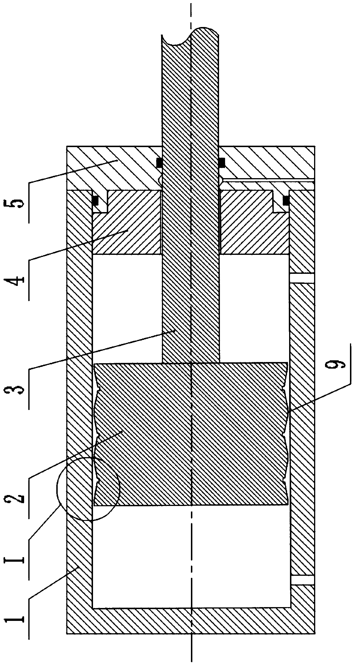
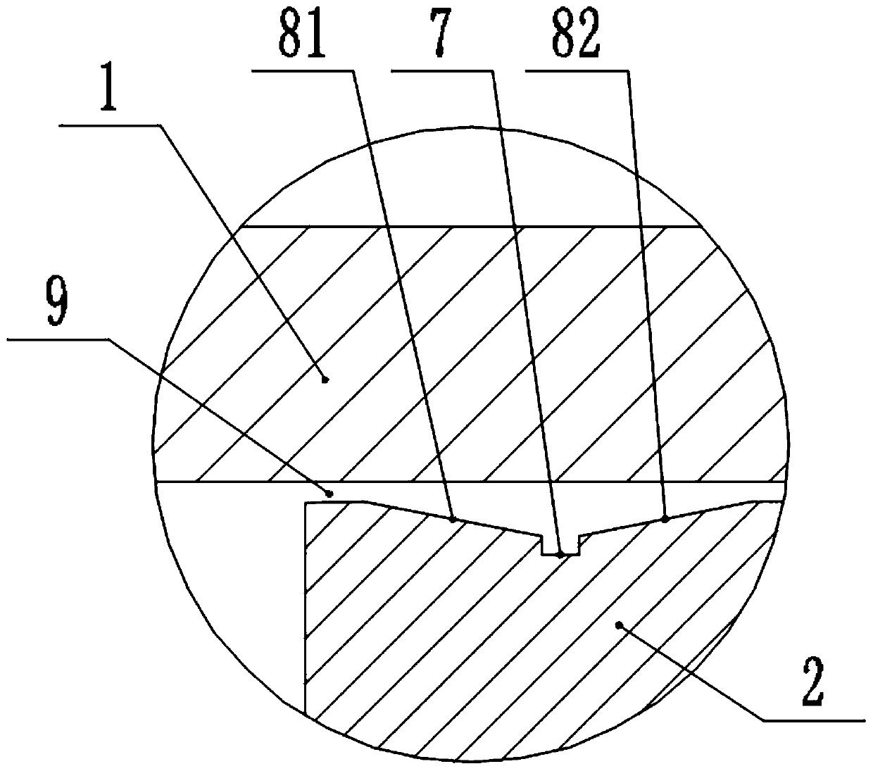
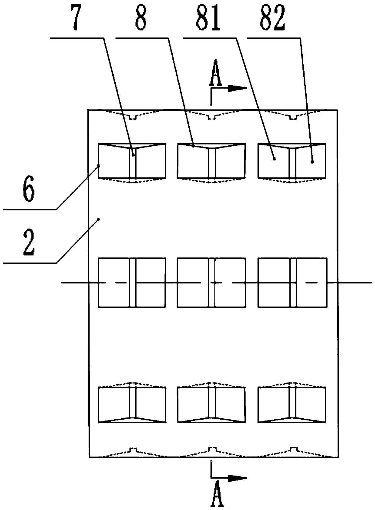
[0021] Such as figure 1 As shown, the hydraulic cylinder with a gap dynamic seal piston includes a cylinder body 1, a piston 2, a piston rod 3, a guide sleeve 4 and a cylinder head 5; the cylinder body 1 is a barrel-shaped structure with one end open, such as figure 2 As shown, the outer diameter of the piston 2 is matched with the inner diameter of the cylinder 1, there is a slit gap 9 between the outer circumferential surface of the piston 2 and the inner wall of the cylinder 1, and the piston 2 and the piston rod 3 are arranged coaxially Installed inside the cylinder body 1, the guide sleeve 4 and the cylinder head 5 are sequentially installed on the cylinder mouth of the cylinder body 1 from the inside to the outside, the piston rod 3 runs through the guide sleeve 4 an...


PUM


Abstract

The invention discloses a hydraulic cylinder with a gap dynamic sealing piston. The hydraulic cylinder comprises a cylinder body, a piston, a piston rod, a guide sleeve and a cylinder cover; a grooveset which is arranged along the circumferential direction of the piston is arranged on the outer circumferential surface of the piston, the groove set comprises a plurality of concave grooves which are uniformly distributed in the circumferential direction, the inner concave groove comprises an oil groove and a V-shaped conical surface, the oil groove is located in the middle of the inner concavegroove, the length trend of the oil groove is arranged in the circumferential direction of the piston, the V-shaped conical surface is symmetrically arranged on the front conical surface and the rearconical surface in a front-back symmetry manner relative to the oil groove, the top ends of the front conical surface and the rear conical surface are connected with the outer circumferential surfaceof the piston respectively , the bottom ends of the front conical surface and the rear conical surface are connected with the top ends of the ledges of the oil groove respectively, the top end of thefront conical surface or the top end of the rear conical surface is not connected with the front end surface of the piston, and the top end of the rear conical surface or the top end of the front conical surface is not connected with the rear end surface of the piston. According to the hydraulic cylinder with the gap dynamic sealing piston, liquid lubrication between the piston and the cylinder body can be ensured, and the phenomena of piston jammed and piston scraping are avoided on the premise of effectively reducing internal leakage of the piston.

Description

technical field [0001] The invention relates to a hydraulic cylinder, in particular to a hydraulic cylinder with a gap dynamic sealing piston, which belongs to the technical field of hydraulic oil cylinders. Background technique [0002] A hydraulic cylinder is a hydraulic actuator that converts hydraulic energy into mechanical energy and performs linear reciprocating motion (or swing motion), and is widely used in various mechanical hydraulic systems. [0003] A hydraulic cylinder usually includes a cylinder barrel, a cylinder head, a piston, a piston rod and a sealing device. The seal between the piston and the cylinder barrel of a traditional hydraulic cylinder usually adopts a sealing ring installation groove arranged in the circumferential direction of the piston and a sealing ring mounted on the sealing ring. The rubber sealing ring in the installation groove is realized, but this traditional sealing structure is prone to crawling at low speeds, and will shorten the se...

Claims


Application Information

Patent Timeline
Patent Type & Authority Applications(China)
IPC IPC(8): F15B15/14F15B15/20F15B15/22
CPCF15B15/1423F15B15/1447F15B15/1428F15B15/1433F15B15/20F15B15/22
Inventor 韩翔陆海峰夏春徐经顾刘子毅张元越陈凤腾
Owner XUZHOU UNIV OF TECH
Learn More