Fabric disinfecting device

A technology for disinfection equipment and fabrics, which is applied in disinfection, sanitary equipment for toilets, water supply devices, etc., and can solve the problems of long disinfection process, unfavorable quality, and large water absorption of fabrics.

Active Publication Date: 2018-06-22
NINGBO WENZE TEXTILE CO LTD
View PDF7 Cites 2 Cited by
  • Summary
  • Abstract
  • Description
  • Claims
  • Application Information

AI Technical Summary

Problems solved by technology

The above disinfection process is relatively long, and the cloth will absorb a lot of water through soaking, and the soaking time of the disinfectant on the cloth is long, so it is not conducive to quality assurance

Method used


Image

  • Fabric disinfecting device
  • Fabric disinfecting device

Examples


Embodiment 1

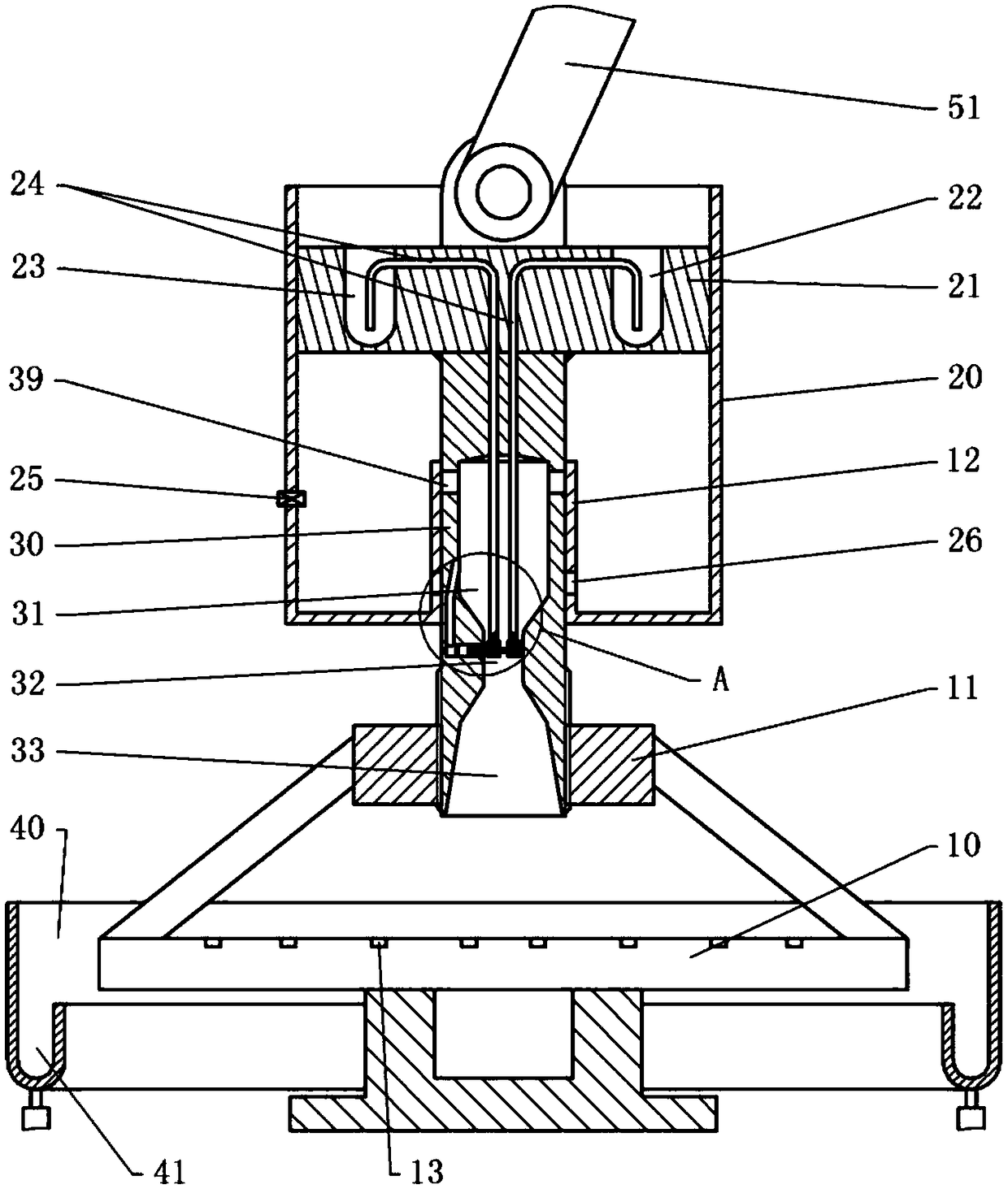
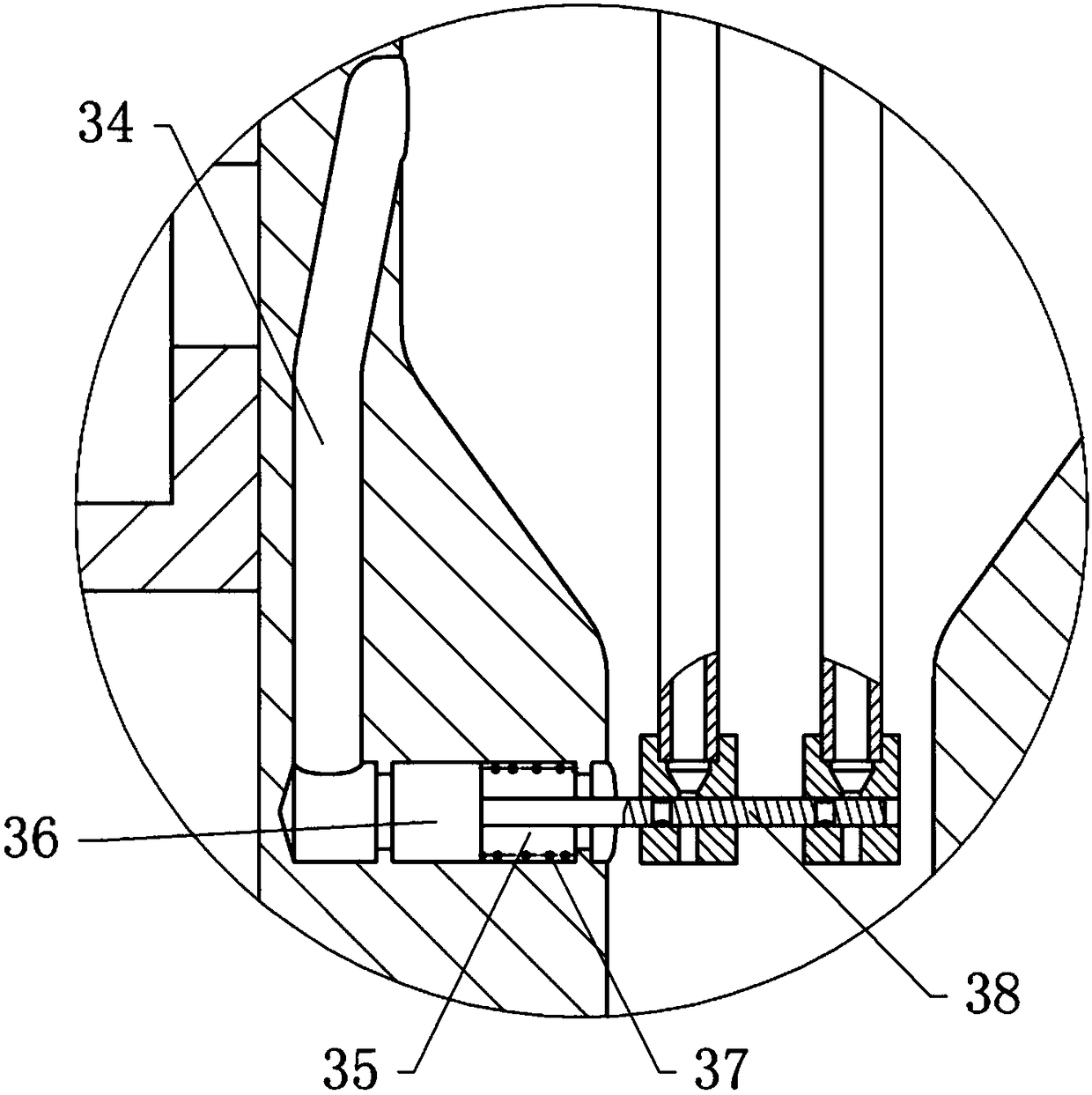
[0025] Such as figure 1 , figure 2 As shown, the cloth disinfection equipment includes a frame, an air box 20, a disinfection table 10 and a motor, the air box 20 and the motor are fixedly installed on the frame, the disinfection table 10 is a square platform, and the surface of the disinfection table 10 is provided with some The guide groove 13 is extended from the center to the periphery, and the disinfection table 10 is rotatably connected to the frame, and the disinfection table 10 is located under the air box 20 . A piston 21 is arranged in the air box 20 , the piston 21 can slide up and down in the air box 20 , and the upper part of the air box 20 is closed by the piston 21 . A crank is fixed on the output shaft of the motor, and the crank and the piston 21 are connected by a connecting rod 51, so that the crank, the piston 21 and the connecting rod 51 form a crank slider 36 mechanism; when the motor rotates, the piston 21 is driven up and down in the air box 20 recip...

Embodiment 2

[0031] The difference between the second embodiment and the first embodiment is that the pressure detection device in the second embodiment includes a controller and a pressure sensor, the valve is a solenoid valve, and both the pressure sensor and the solenoid valve are electrically connected to the controller. When the pressure at the throat drops, the pressure sensor will feed back a signal to the controller, and at the same time, the controller will send an execution signal to the solenoid valve, and the solenoid valve will open.


PUM


Abstract

The invention relates to the field of spinning equipment, and specifically discloses a fabric disinfecting device. The device comprises a rack, an air box, a disinfecting table rotatably connected tothe rack, and a motor, wherein a piston is arranged in the air box; a crank is fixedly connected to an output shaft of the motor; the crank and the piston form a crank sliding block mechanism; an airpipe is fixed to the bottom of the piston, and the air pipe comprises an inlet section, a throat channel and an expanding section which are sequentially arranged from top to bottom; a sleeve which sleeves the air pipe is fixedly arranged in the air box; the air pipe is provided with an air inlet which is communicated with the inlet section; an air guide hole which is communicated with the air inlet is formed in the sleeve; a liquid groove is formed in the piston and is communicated with the throat channel through a guide pipe; a valve is arranged at the end part, in the throat channel, of theguide pipe; a pressure detecting device for controlling the valve to open and close is arranged at the throat part; a spiral groove is formed in the periphery of the lower part of the air pipe; a driving ring which is fixed to the disinfecting platform is arranged above the disinfecting platform; a spiral convex edge which fits the spiral groove is arranged on the driving ring. The device is capable of timely dewatering a fabric after disinfecting.

Description

technical field [0001] The invention relates to the field of textile equipment, in particular to a cloth disinfection equipment. Background technique [0002] With the gradual improvement of people's quality of life, people's demand for clothes is gradually increasing. In the textile and dyeing industry, the cloth will be sterilized before leaving the factory. The current disinfection method is mainly by soaking the cloth in the disinfectant, and stirring the cloth in the disinfectant, so that the disinfectant can fully enter the cloth. However, during the long-term soaking process of the cloth, the fibers in the cloth will be gradually dissolved by water, which will lead to a decrease in the strength of the cloth. When sterilizing the cloth by soaking, the workers will stir the cloth to make the disinfectant evenly distributed in the water, but at the same time, it will also rub the cloth, so that the cloth is prone to messy wrinkles after being dried out of the water. Ir...

Claims


Application Information

Patent Timeline
Patent Type & Authority Applications(China)
IPC IPC(8): A61L2/18A61L2/26
CPCA61L2/18A61L2/26A61L2202/26
Inventor 孙文清
Owner NINGBO WENZE TEXTILE CO LTD
Why Eureka
Try Eureka