
Dynamic compensation method for MEMS (Micro Electro Mechanical System) gyroscope Z-axis zero offset on the basis of Kalman filtering

A Kalman filter and dynamic compensation technology, applied to instruments, measuring devices, etc., can solve problems such as large deviation in heading angle measurement and inaccurate Z-axis measurement values

Pending Publication Date: 2018-10-19
无锡凌思科技有限公司
View PDF6 Cites 8 Cited by
  • Summary
  • Abstract
  • Description
  • Claims
  • Application Information

AI Technical Summary

Problems solved by technology

[0002] IMU modules based on MEMS gyroscopes all have zero bias problems. For the zero bias of the X-axis and Y-axis, the measured values ​​​​of the X-axis and Y-axis accelerometers can be calibrated using the Kalman filter algorithm, while the Z-axis cannot pass this. method calibration, so the Z-axis measurement value of MEMS-based IMU modules on the market is generally inaccurate, and the result is that the measurement of the heading angle will have a large deviation, which is largely due to the zero of the Z-axis cause

Method used


Image

  • Dynamic compensation method for MEMS (Micro Electro Mechanical System) gyroscope Z-axis zero offset on the basis of Kalman filtering
  • Dynamic compensation method for MEMS (Micro Electro Mechanical System) gyroscope Z-axis zero offset on the basis of Kalman filtering
  • Dynamic compensation method for MEMS (Micro Electro Mechanical System) gyroscope Z-axis zero offset on the basis of Kalman filtering

Examples


Embodiment Construction

[0045] The preferred embodiments of the present invention will be described below in conjunction with the accompanying drawings. It should be understood that the preferred embodiments described here are only used to illustrate and explain the present invention, and are not intended to limit the present invention.

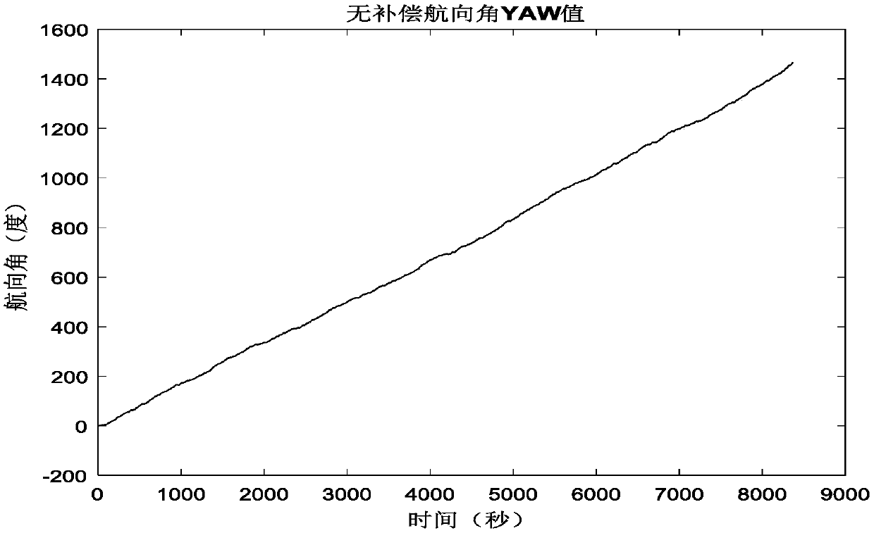
[0046] Through the long-term tracking measurement of the MEMS gyroscope, it is found that the zero bias of the MEMS gyroscope has the characteristics of short-term stability and long-term slight change. Taking one of the typical measurement values ​​as an example, the measured heading angle value without compensation is as follows: figure 1 shown.

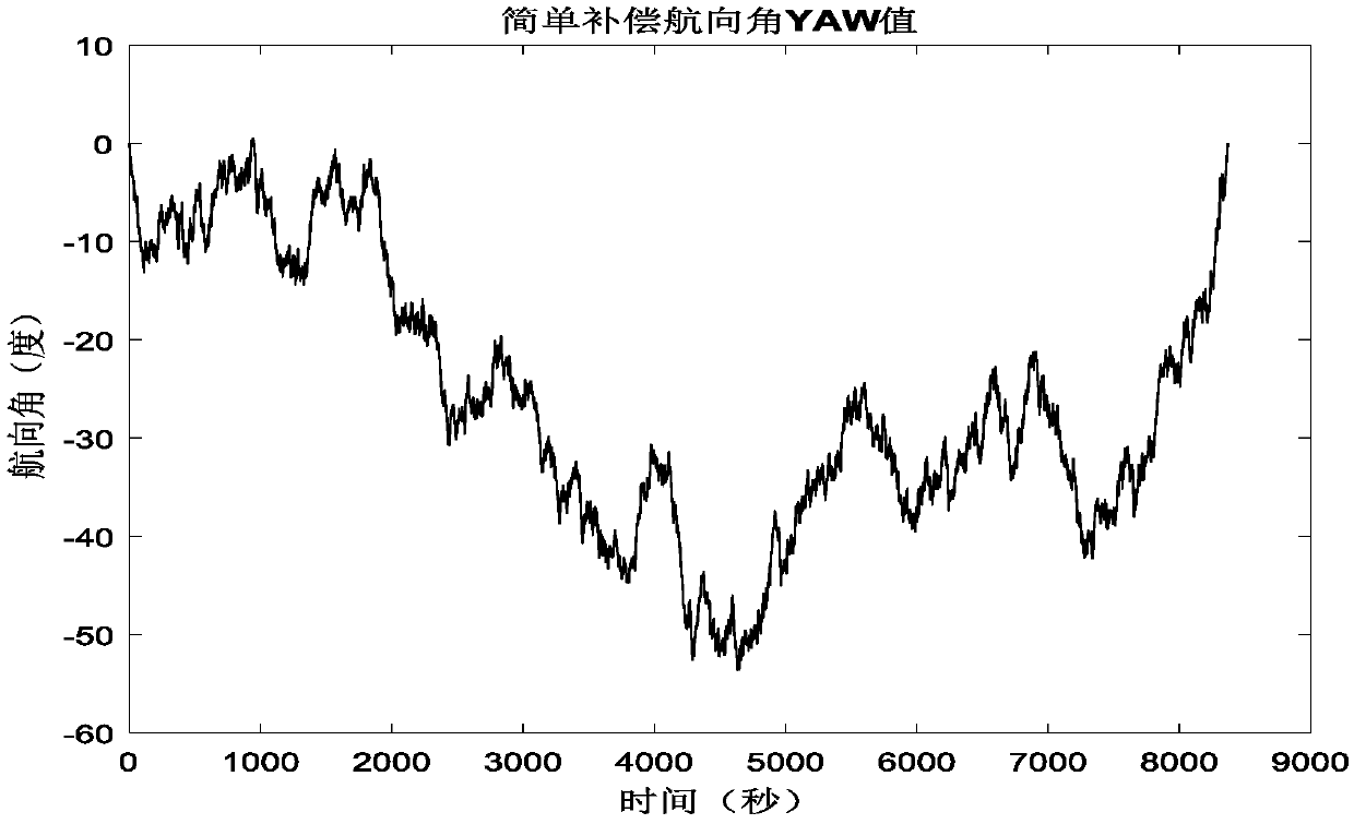
[0047] After measuring the slope, do simple compensation to get the heading angle value as figure 2 As shown, it can be seen from the above figure that simple compensation cannot solve the zero offset problem of the Z axis well.

[0048] This patent adopts a dynamic adaptive Kalman compensation algorithm. By capturing ...


PUM


Abstract

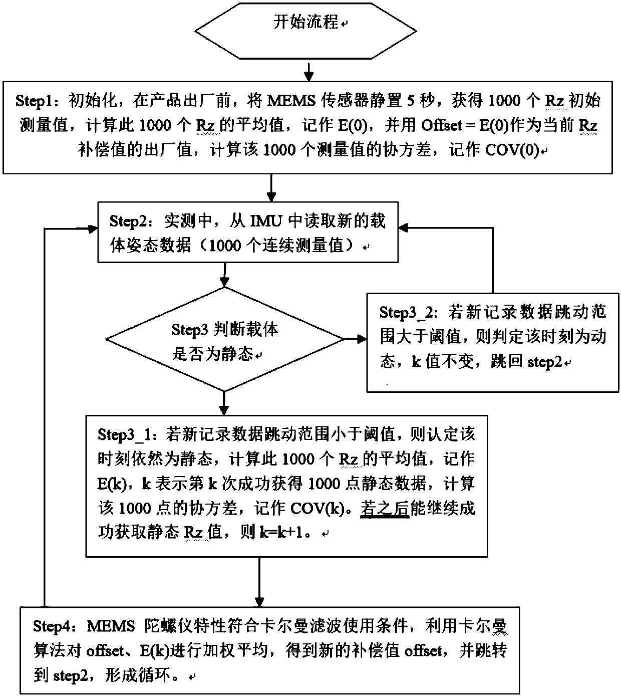
The invention discloses a dynamic compensation method for an MEMS (Micro Electro Mechanical System) gyroscope Z-axis zero offset on the basis of Kalman filtering. The dynamic compensation method mainly comprises the following steps: S1: when an IMU (Inertial Measurement Unit) is under a static state, obtaining carrier gesture data, and calculating to obtain the compensation value of MEMS gyroscopeZ-axis angular speed Rz through the obtained carrier gesture data to serve as an initial compensation value Offset; S2: in actual measurement, reading new carrier gesture data from the IMU; S3: judging whether the carrier is under the static state or not; S4: calculating by a Kalman algorithm, obtaining a new compensation value of the MEMS gyroscope Z-axis angular speed Rz, updating the Offset, and then, jumping to S2 to form circulation. According to the dynamic compensation method for the MEMS gyroscope Z-axis zero offset on the basis of the Kalman filtering, the Z-axis zero offset is dynamically captured, the Kalman algorithm is applied for carrying out dynamic compensation, the accuracy of the MEMS gyroscope is improved, a gyroscope Z-axis error is reduced, and meanwhile, the measurement error of a course angle YAW is reduced.

Description

technical field [0001] The invention relates to the field of dynamic compensation of Z-axis bias of MEMS gyroscopes, in particular to a method for dynamic compensation of Z-axis bias of MEMS gyroscopes based on Kalman filtering. Background technique [0002] IMU modules based on MEMS gyroscopes all have zero bias problems. For the zero bias of the X-axis and Y-axis, the measured values ​​​​of the X-axis and Y-axis accelerometers can be calibrated using the Kalman filter algorithm, while the Z-axis cannot pass this. method calibration, so the Z-axis measurement value of MEMS-based IMU modules on the market is generally inaccurate, and the result is that the measurement of the heading angle will have a large deviation, which is largely due to the zero of the Z-axis Bias caused. [0003] This patent dynamically captures the zero offset of the Z-axis, and uses the Kalman algorithm to dynamically compensate the zero offset, thereby improving the accuracy of the MEMS gyroscope, r...

Claims


Application Information

Patent Timeline
IPC IPC(8): G01C25/00
CPCG01C25/005
Inventor 王雷蒋佩宇赵炜刘飞
Owner 无锡凌思科技有限公司
Learn More