
Optical fiber locking structure and connector

A locking mechanism and optical fiber technology, applied in light guides, optics, instruments, etc., can solve problems such as unsuitable for popularization and high cost, and achieve the effect of simple structure and low cost

Pending Publication Date: 2018-10-19
CENTURY OPTICOMM CO LTD
View PDF1 Cites 0 Cited by
  • Summary
  • Abstract
  • Description
  • Claims
  • Application Information

AI Technical Summary

Problems solved by technology

The elastic wall is usually set in the base as a whole. When damage occurs, the base needs to be replaced as a whole. The cost is high and it is not suitable for popularization.

Method used


Image

  • Optical fiber locking structure and connector
  • Optical fiber locking structure and connector
  • Optical fiber locking structure and connector

Examples


Embodiment Construction

[0043] The implementation of the present invention will be illustrated by specific specific examples below, and those skilled in the art can easily understand other advantages and effects of the present invention from the contents disclosed in this specification.

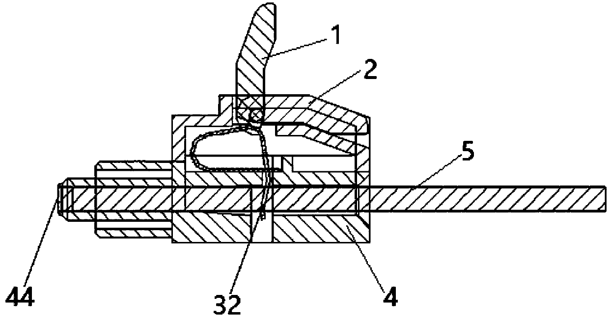
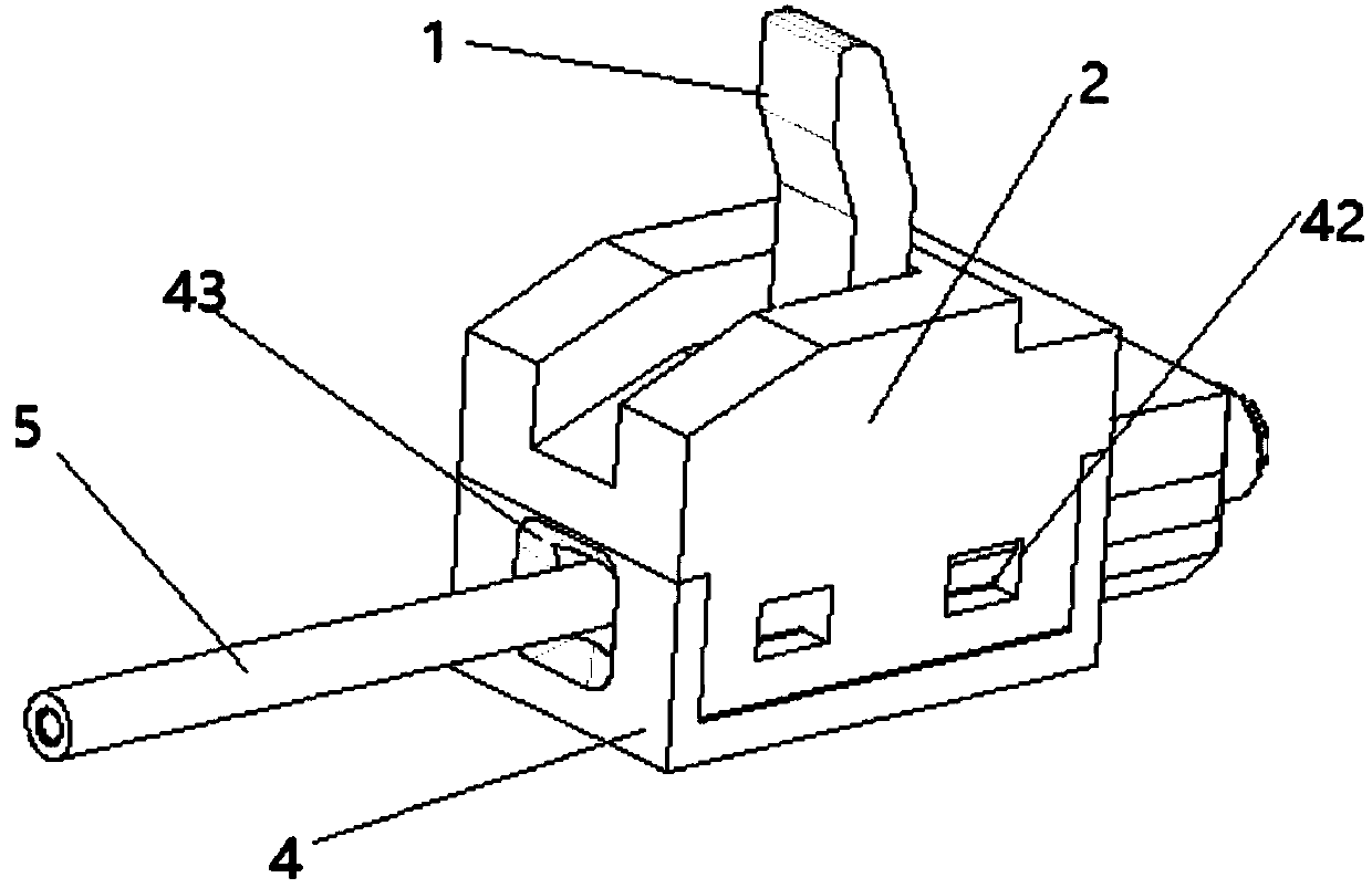
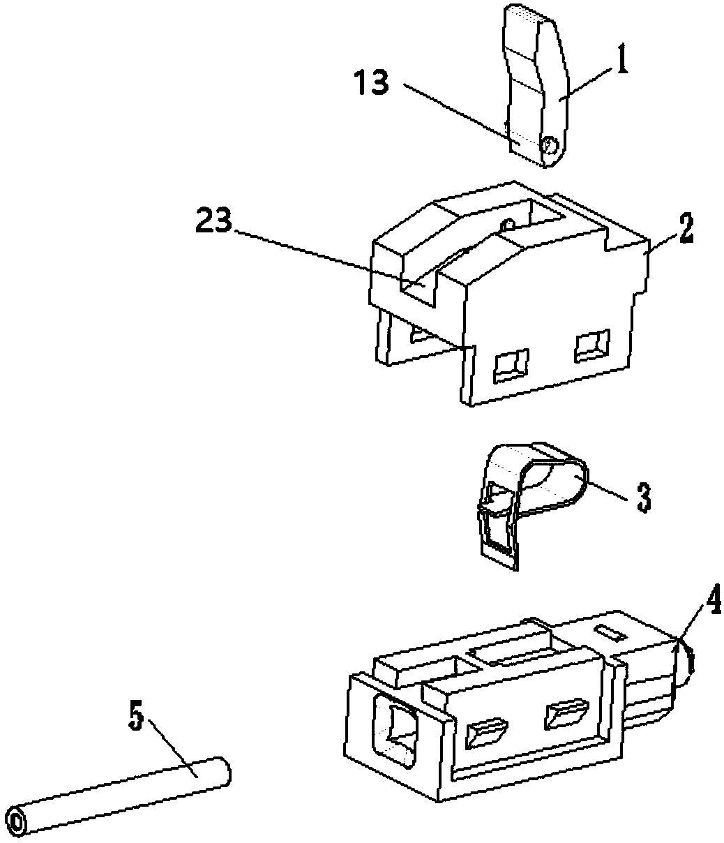
[0044] see Figure 1 to Figure 4 . It should be noted that the structures, proportions, sizes, etc. shown in the drawings attached to this specification are only used to match the content disclosed in the specification, for those who are familiar with this technology to understand and read, and are not used to limit the implementation of the present invention. Limiting conditions, so there is no technical substantive meaning, any modification of structure, change of proportional relationship or adjustment of size, without affecting the effect and purpose of the present invention, should still fall within the scope of the present invention. The disclosed technical content must be within the scope covered. At the sa...


PUM


Abstract

The present invention provides an optical fiber locking structure which comprises a seat body which is internally provided with a fiber passing portion and comprises a spring groove which passes the spring groove and is embedded to an upper part of the fiber passing portion, a cover body which is arranged on the seat body and is connected to the seat body, a cage spring which is embedded in the spring groove and has an inner hole which communicates with the fiber passing portion for the optical fiber to pass through, and a force applying member which comprises a head part and is rotatably fixed to an upper portion of the cover body, wherein the force applying member is rotated to press the cage spring to enlarge an inner diameter of the inner hole, and the cage spring locks the optical fiber in springback due to loose and deformation. The optical fiber locking structure also comprises a connector including the above locking structure. The structure of the optical fiber locking structure is simple, a split design is designed, when the cage spring or the force applying member fails due to multiple uses, the purpose of repair can be achieved by replacing a damaged component, and the optical fiber locking structure has the advantages of low cost and repeated uses compared with an integrated optical fiber locking mechanism.

Description

technical field [0001] The invention relates to a device for connecting between optical devices, in particular to an optical fiber locking mechanism and a connector. Background technique [0002] Fiber optic connectors are an essential part of virtually all fiber optic communication systems. For example, such connectors can be used to splice fiber segments into longer lengths; connect fibers to active devices such as transceivers, detectors, and repeaters; or connect fibers to on passive devices. The main function of a fiber optic connector is to hold the two fiber ends so that the core of one fiber is axially aligned with the core of the other fiber, or coupled to an optical component; thus, all the light from one fiber as possible Efficiently couples to another fiber or optical element. [0003] However, most of the existing optical fiber connectors are designed for glass optical fiber materials, and the installation accuracy of glass optical fibers is high. As a result...

Claims


Application Information

Patent Timeline
IPC IPC(8): G02B6/38
CPCG02B6/3855
Inventor 王承伟
Owner CENTURY OPTICOMM CO LTD
Learn More