Bonding device

A technology of bonding and adhesives, which is applied to the seams of textile materials, textiles and papermaking, and tools for sewing clothes, etc. It can solve the problem of uneven overlapping of the lower sheet and the upper sheet and difficult to transport stably Problems such as the lower sheet and the upper sheet, difficulty in maintaining the positional relationship between the right end of the lower sheet and the left end of the upper sheet

Active Publication Date: 2018-10-23
BROTHER KOGYO KK
View PDF4 Cites 1 Cited by
  • Summary
  • Abstract
  • Description
  • Claims
  • Application Information

AI Technical Summary

Problems solved by technology

However, when the force of the operator holding the lower sheet and the upper sheet is too large, there is a possibility that the upper sheet and the lower sheet are pulled by the operator and deviate in the left-right direction, and the upper sheet and the lower sheet wrinkle
When the force holding the lower sheet and the upper sheet by the operator is too small, there is a possibility that the right end of the lower sheet deviates from the lower sheet guide, and the left end of the upper sheet deviates from the upper sheet guide, causing the lower sheet to The amount of overlap between the top sheet and the top sheet is uneven
Therefore, it may be difficult for the bonding device to maintain the positional relationship between the right end of the lower sheet and the left end of the upper sheet with respect to the nozzles, and it may be difficult to stably convey the lower sheet and the upper sheet.

Method used


Image

  • Bonding device
  • Bonding device
  • Bonding device

Examples


Embodiment Construction

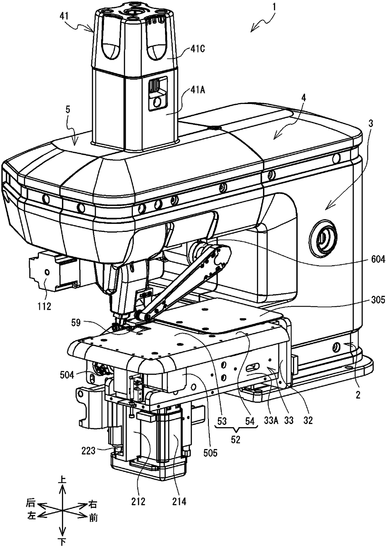
[0052] Embodiments of the present invention will be described. The following description uses left and right, front and rear, and up and down shown by arrows in the drawings. Bonding device 1 utilizes adhesive Z (refer to Figure 22 ) to bond the two sheets together. Two sheets are lower sheet 8 and upper sheet 6 (referring to Figure 18 ). The upper sheet 6 overlaps the lower sheet 8 from above. The lower sheet 8 and the upper sheet 6 are, for example, flexible cloth. The bonding apparatus 1 of the present embodiment bonds the right end portion of the lower sheet 8 , that is, the lower specified end portion 8A, and the left end portion of the upper sheet 6 , that is, the upper specified end portion 6A with the adhesive Z.

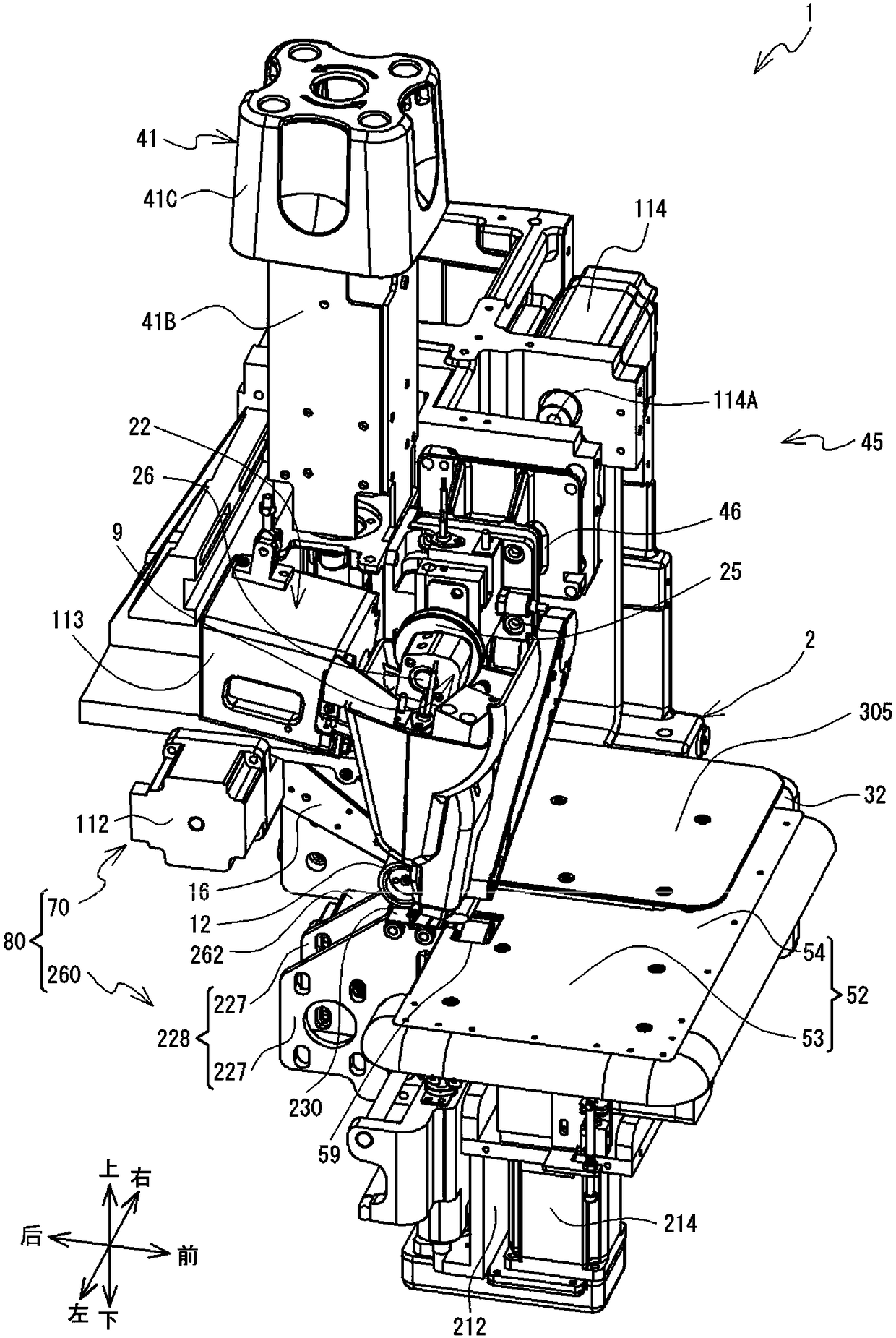
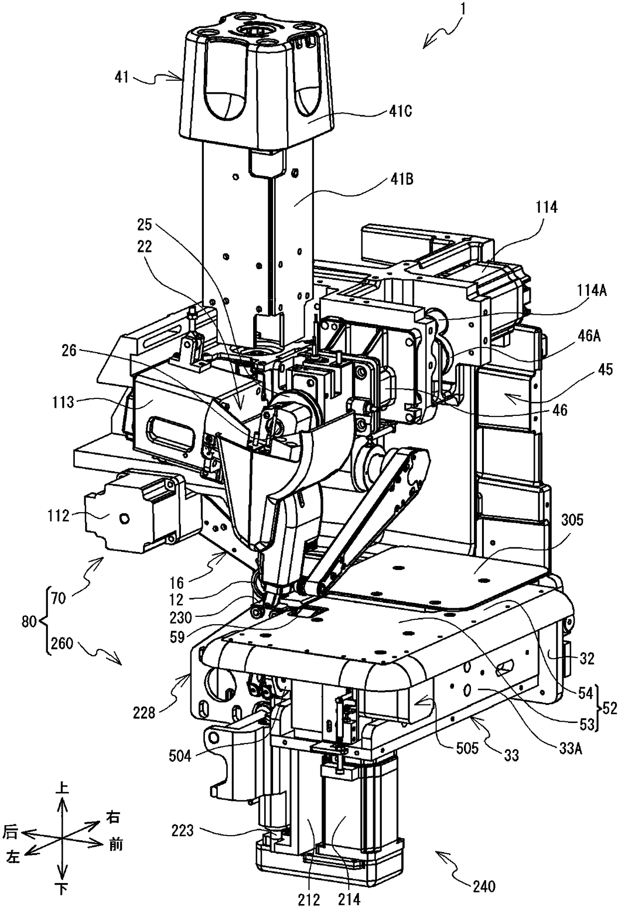
[0053] refer to Figure 1 to Figure 14 The mechanical structure of the bonding apparatus 1 will be described. Such as Figure 1 ~ Figure 3 As shown, the bonding device 1 has a base part 2 , a pillar part 3 , an arm part 4 and a head part 5 . The b...


PUM


Abstract

The present invention relates to a bonding device. The bonding device includes a lower clamp roller, an upper clamp roller, a support member, a lower detection portion, and an upper detection portion.The lower clamp roller and the upper clamp roller can rotate with an axial direction thereof being the front-rear direction. A lower specified end portion, which is a right end portion of the lower sheet, is clamped between the lower clamp roller and the support member. An upper specified end portion, which is a left end portion of the upper sheet, is clamped between the upper clamp roller and the support member. The lower detection portion detects whether the lower specified end portion is located at a lower detection position, which is a predetermined position. The upper detection portion detects whether the upper specified end portion is located at an upper detection position, which is a predetermined position. The bonding device switches a rotating direction of the lower clamp rollerand the upper clamp roller in accordance with detection results of the lower detection portion and the upper detection portion.

Description

technical field [0001] The invention relates to a bonding device. Background technique [0002] A bonding device is known for bonding two sheets to each other by means of an adhesive. The bonding apparatus disclosed in Japanese Patent Laid-Open No. 122262 of 2011 includes a nozzle, an upper transport roller, a belt, and guide members for both edges. Nozzles are used to discharge adhesive to the lower sheet. The upper conveying roller conveys the lower sheet and the upper sheet while pressing the upper sheet and the adhesive-coated lower sheet between the upper conveyance roller and the belt. The guide member for both edges has a lower sheet guide and an upper sheet guide. The operator inserts the right end of the lower sheet into the lower sheet guide for positioning, and inserts the left end of the upper sheet into the upper sheet guide for positioning. [0003] In the bonding apparatus described above, the operator needs to hold the conveyed lower sheet and upper sheet...

Claims


Application Information

Patent Timeline
Patent Type & Authority Applications(China)
IPC IPC(8): A41H43/04
CPCA41H43/04B29C65/4815B29C65/524B29C65/7832B29C65/7894B29C66/1122B29C66/43B29C66/729B29C66/81465B29C66/8167B29C66/83413B29C66/845B29C66/872B29C66/9672D06H5/00
Inventor 柴田到岩越弘恭梅田和俊
Owner BROTHER KOGYO KK
Why Eureka
Try Eureka