Push rod device of annealing furnace shovel loader

A push rod device and push rod technology, applied in the direction of furnaces, conveyors, furnace components, etc., can solve problems such as prone to expansion and contraction

Inactive Publication Date: 2005-02-23
OWENS-BROCKWAY GLASS CONTAINER INC
View PDF4 Cites 0 Cited by
  • Summary
  • Abstract
  • Description
  • Claims
  • Application Information

AI Technical Summary

Problems solved by technology

The width of the conveyor belt that carries the glass containers and makes the glass containers pass through the lehr determines the required width of the push rod device of the lehr loader connected to this lehr, and the prior art is used for this push rod device The full width rod is prone to stretching and contracting

Method used


Image

  • Push rod device of annealing furnace shovel loader
  • Push rod device of annealing furnace shovel loader
  • Push rod device of annealing furnace shovel loader

Examples


Embodiment Construction

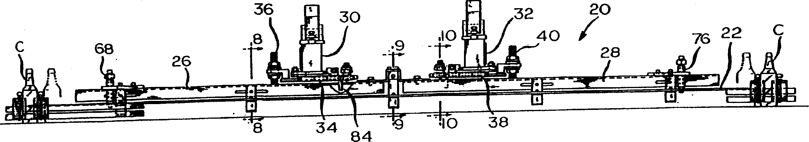
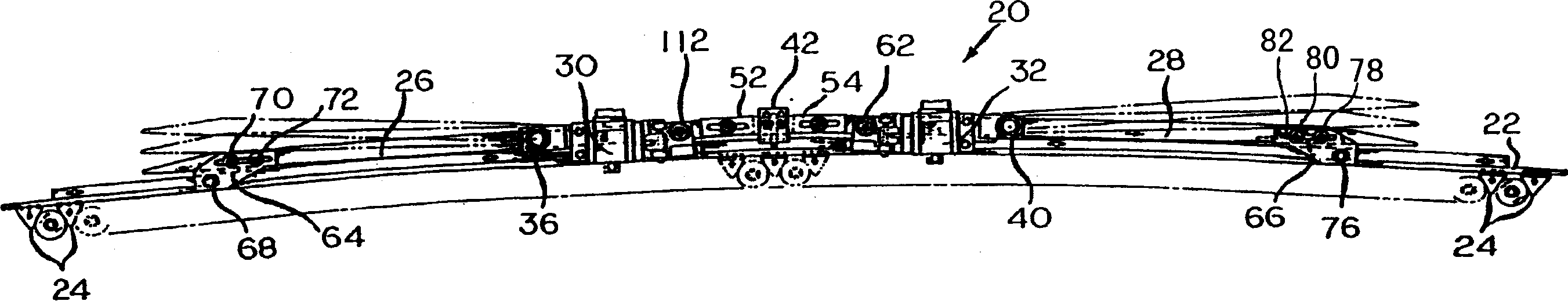
[0019] According to a preferred embodiment of the present invention, in figure 1 with figure 2 , reference numeral 20 generally denotes such a push rod device. This push rod arrangement 20 comprises a generally horizontally extending one-piece rod 22 which extends across the entire width of the interior of a lehr (not shown). This sleeve bar 22 is provided with a set of spaced apart generally triangular teeth 24 forming a sleeve for engagement with the newly formed glass container C to be annealed.

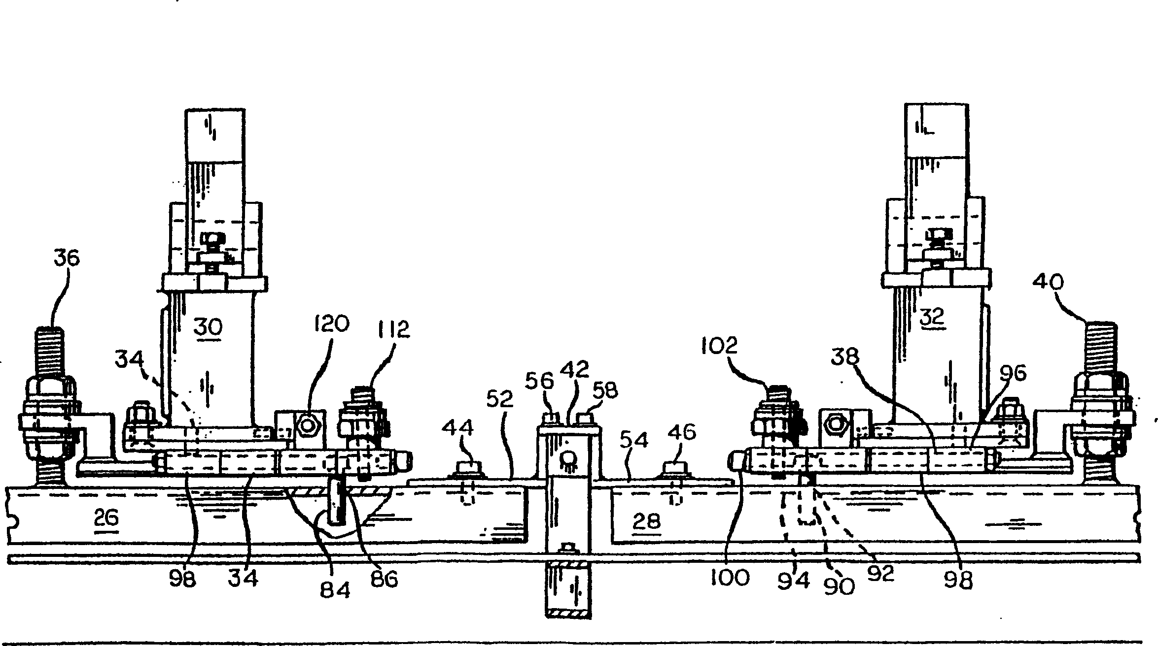
[0020] The sleeve rod 22 is supported on a set of generally horizontally extending push rods arranged end to end, shown as push rods 26 and 28 . Push rods 26 and 28 are connected to downwardly extending beams 30, 32, respectively, which are part of the uppermost carriage of a prior art three-axis annealing loader, but this uppermost carriage is not shown. The push rod 26 is suspended from a generally horizontally extending flange 34 secured to the bottom of the beam 30 by thre...


PUM


Abstract

A pusher bar assembly (20) having a flexible, horizontally extending pocket bar (22) of sufficient longitudinal extent to push a linear array of glass containers on a cross-conveyer transversely of the cross-conveyor into an annealing lehr. The pocket bar, which engages the containers to be pushed, is disengageably secured to a pair of aligned horizontal pusher bars (26, 28), whose adjacent ends are spaced apart from one another. The pusher bars are secured, respectively, to first and second downwardly extending beams (30, 32).

Description

technical field [0001] The present invention relates to a pusher device of an object conveying device used for conveying a group of laterally placed objects arranged in a straight line on a conveyor belt into an object processing unit. In particular, it relates to a pusher device for conveying newly formed glass containers to a level on a conveyor belt of an annealing furnace, which is often referred to as an annealing furnace, and having the aforementioned characteristics. Conveyor equipment for loaders or object lifters. Background technique [0002] Among the U.S. Patent No. 5,044,488 patented by Bolin, a lehr loader or object elevator is disclosed, which has a set of vertical carriages, wherein the lowermost carriage is supported by a support member in which the lehr is housed. on the level above the bottom plate. This lowermost carriage is movable toward an adjacent lehr, thereby feeding into the lehr a line-up of glass containers on a conveyor belt, referred to in th...

Claims


Application Information

Patent Timeline
IPC IPC(8): B65G47/82C03B35/06C03B35/10F27D3/06
CPCC03B35/10B65G2201/0244
Inventor J·H·沃恩
Owner OWENS-BROCKWAY GLASS CONTAINER INC
Why Eureka
Try Eureka