Gear milling machine used for machining straight cone gear

A gear milling machine and gear technology, which is applied to gear tooth manufacturing devices, gear cutting machines, components with teeth, etc., can solve problems such as troublesome trimming operations, inconvenient gear chamfering, trimming, and affecting gear processing efficiency. , to achieve the effect of improving processing efficiency

Active Publication Date: 2018-10-23
CHONGQING HANYUAN MACHINERY
View PDF7 Cites 1 Cited by
  • Summary
  • Abstract
  • Description
  • Claims
  • Application Information

AI Technical Summary

Problems solved by technology

[0002] Gear milling machine is a kind of equipment for processing gears. Its main function is to mill the gear surface. Before milling the gear surface, it is necessary to install cutting tools on the gear milling machine. The gear is in the preliminary processing After the completion, it is necessary to perform chamfering and edge trimming operations on the teeth on the gear, but the traditional chamfering and edge trimming operations are troublesome, and it is inconvenient to chamfer and edge trim the gears, which seriously affects the processing efficiency of the gears. A gear milling machine for processing straight bevel gears that facilitates gear chamfering and edge trimming

Method used


Image

  • Gear milling machine used for machining straight cone gear
  • Gear milling machine used for machining straight cone gear

Examples


Embodiment Construction

[0016] The following will clearly and completely describe the technical solutions in the embodiments of the present invention with reference to the accompanying drawings in the embodiments of the present invention. Obviously, the described embodiments are only some, not all, embodiments of the present invention.

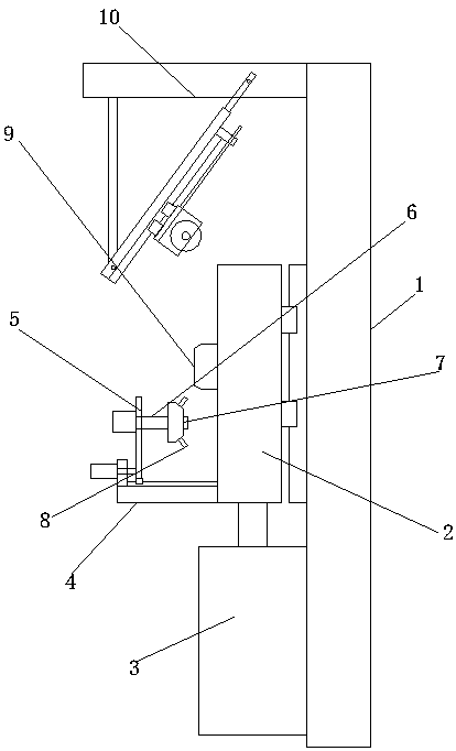
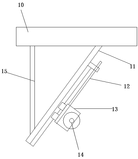
[0017] refer to Figure 1-2 , a gear milling machine for processing straight bevel gears, comprising a mounting base 1, a mounting plate 2 is slidably installed above the mounting base 1, and a cylinder 3 fixedly connected to the mounting base 1 is mounted on one side of the mounting plate 2, and the installation An L-shaped connecting plate 4 is welded vertically above the end of the plate 2 close to the cylinder 3, and a movable plate 5 is vertically slid on the side of the L-shaped connecting plate 4 away from the cylinder 3, and a rotating shaft 6 is vertically sleeved on the movable plate 5, and the rotating shaft 6 is close to the One end of the mounting plate ...


PUM


Abstract

The invention discloses a gear milling machine used for machining a straight cone gear. The machine comprises a mounting base, a mounting plate is arranged on the upper portion of the mounting base ina sliding manner, one side of the mounting plate is provided with an air cylinder fixedly connected with the mounting base, an L-shaped connecting plate is perpendicularly welded to the position above the end, close to the air cylinder, of the mounting plate, the side, away from the air cylinder, of the L-shaped connecting plate is perpendicularly provided with a movable plate in a sliding manner, the movable plate is perpendicularly sleeved with a rotating shaft, the end, close to the mounting plate, of the rotating shaft is fixedly sleeved with a round-table-shaped rotating disc, driving levers are welded to the outer ring of the rotating disc in the axis line direction at equal distances, a positioning column is welded to the position above the mounting plate, the end, away from the air cylinder, of the mounting plate is perpendicularly welded with a supporting column, and the side, close to the mounting plate, of the supporting column is welded with an inclined guide plate. The gear which is preliminarily machined is automatically and rapidly subjected to chamfering and edge trimming operation, the gear machining efficiency is improved, manpower and material resources are saved, the gear surface is smooth and free of burrs, and the gear quality and attractiveness are improved.

Description

technical field [0001] The invention relates to the technical field of gear milling machines, in particular to a gear milling machine for processing straight bevel gears. Background technique [0002] Gear milling machine is a kind of equipment for processing gears. Its main function is to mill the gear surface. Before milling the gear surface, it is necessary to install cutting tools on the gear milling machine. The gear is in the preliminary processing After the completion, it is necessary to perform chamfering and edge trimming operations on the teeth on the gear, but the traditional chamfering and edge trimming operations are troublesome, and it is inconvenient to chamfer and edge trim the gears, which seriously affects the processing efficiency of the gears. A gear milling machine for machining straight bevel gears which facilitates gear chamfering and edge trimming. Contents of the invention [0003] The object of the present invention is to propose a gear milling m...

Claims


Application Information

Patent Timeline
Patent Type & Authority Applications(China)
IPC IPC(8): B23F5/20B23F23/00
CPCB23F5/20B23F23/00
Inventor 罗昭成
Owner CHONGQING HANYUAN MACHINERY
Why Eureka
Try Eureka