Municipal gutter inlet internal dredging equipment

A stormwater and municipal technology, applied to waterway systems, water supply devices, drainage structures, etc., can solve the problems of incomplete cleaning of debris, small use range, and high labor costs

Inactive Publication Date: 2021-02-09
森拓建设集团有限公司
View PDF14 Cites 1 Cited by
  • Summary
  • Abstract
  • Description
  • Claims
  • Application Information

AI Technical Summary

Problems solved by technology

Generally, it should be installed at intersections, roadside ditches at a certain distance, and low-lying places with road curbstones to prevent rainwater from overflowing the road or causing water accumulation in roads and low-lying areas to hinder traffic. Sometimes it is easy to cause blockage, so it needs to be cleaned. Generally, manual cleaning is used, and there are also mechanical equipment for cleaning. However, there are still various problems in various cleaning mechanical equipment on the market.
[0003] For example, the authorized announcement number is CN108643336B, a kind of internal dredging equipment for municipal gullies, although it can solve the problems of high labor cost, difficult cleaning, small scope of use and potential safety hazards in the dredging process of existing gullies. , can realize the function of automatic cleaning and dredging of the rainwater outlet, which has the advantages of low labor cost, small cleaning difficulty, wide application range and good safety, etc., but it does not solve the existing problem of not being able to make the machine equipment move freely in the rainwater outlet. If the debris pads up the bottom, the movement cannot be realized, and the scraper provided scrapes up and down, and the debris cannot be completely cleaned up, and after the rainwater outlet is blocked, it cannot be dredged, etc. For this reason, we propose a A kind of internal dredging equipment of municipal storm water outlet

Method used


Image

  • Municipal gutter inlet internal dredging equipment
  • Municipal gutter inlet internal dredging equipment
  • Municipal gutter inlet internal dredging equipment

Examples


Embodiment Construction

[0024] The following will clearly and completely describe the technical solutions in the embodiments of the present invention with reference to the accompanying drawings in the embodiments of the present invention. Obviously, the described embodiments are only some, not all, embodiments of the present invention. Based on the embodiments of the present invention, all other embodiments obtained by persons of ordinary skill in the art without making creative efforts belong to the protection scope of the present invention.

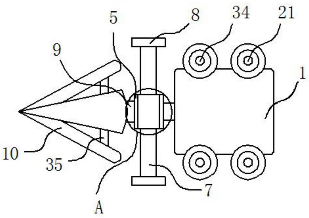
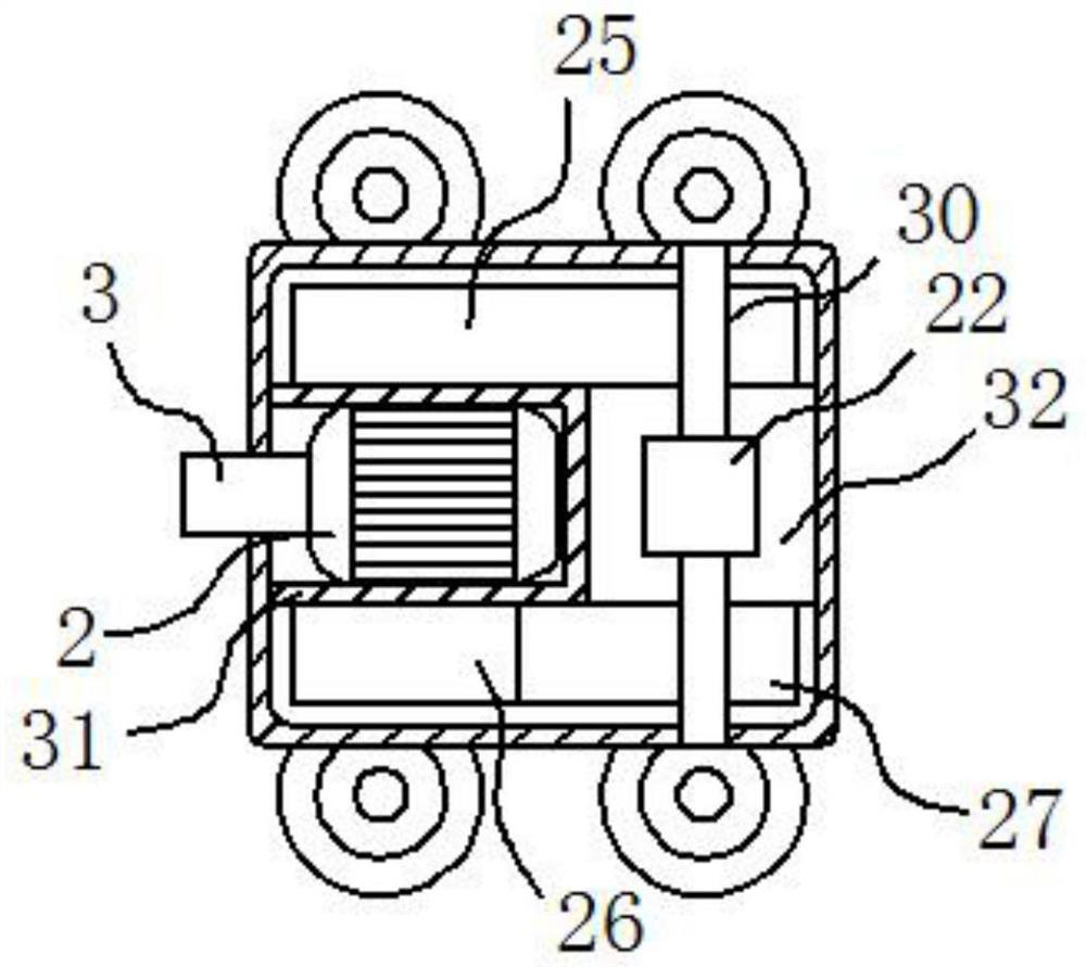
[0025] see Figure 1-Figure 5 , the present invention provides a technical solution: a dredging device inside a municipal gully, including a dredging robot 1, the internal front end of the dredging robot 1 is fixedly installed with a first motor 2, and the output end of the first motor 2 is fixedly connected to a shaft connecting rod 3 , the top of the shaft connecting rod 3 is fixedly connected with the outer ring gear 4, the outer ring gear 4 is movable in t...


PUM


Abstract

The invention discloses municipal gutter inlet internal dredging equipment. The equipment comprises a dredging robot; a first motor is installed in the dredging robot; the first motor drives a first connecting rod and a scraping plate in a connecting plate to rotate through a coupling rod; inclined plates are welded to the connecting plate through a second connecting rod; a second motor is installed in the dredging robot; the second motor drives a first cross beam and a second cross beam to rotate through a first bevel gear; driving wheels are fixedly connected with the two ends of the first cross beam and the two ends of the second cross beam correspondingly; and a first battery pack, a second battery pack and a control module are fixedly installed in the dredging robot. According to themunicipal gutter inlet internal dredging equipment, power is provided for the dredging robot through the second motor, and driving wheels are arranged on the upper portion and the lower portion and can move in a force exerting mode; and the first motor drives the scraping plate to clean impurities left on an inner wall, and the multiple sets of inclined plates are arranged at the front end of thescraping plate and can dredge the blocked impurities.

Description

technical field [0001] The invention belongs to the technical field of municipal engineering, and in particular relates to a device for dredging the interior of a municipal rainwater outlet. Background technique [0002] Urban road gully refers to the water intake structure that the drainage pipe collects the rainwater on the ground. A well with an inlet grate (iron or reinforced concrete). The gully discharges the road surface water collected by the street ditch into the connecting pipe (connecting pipe). The rainwater outlets are located in the street ditches, and the distance between them is determined according to the road surface and precipitation conditions. There are two types of rainwater outlets: flat type and side type. The flat stone setting of the flat type along the street ditch has a fast water inflow speed, but it has to bear the load of the wheel and is easy to be damaged; the side stone setting of the side type along the street ditch enters water from the...

Claims


Application Information

Patent Timeline
Patent Type & Authority Applications(China)
IPC IPC(8): E03F9/00E03F5/04
CPCE03F5/0401E03F9/002Y02A30/60
Inventor 陈军华张甫民马霞
Owner 森拓建设集团有限公司
Why Eureka
Try Eureka