Infrared photoelectric intelligent detector
A detector, infrared light technology, applied in the direction of measuring instrument components, instruments, measuring devices, etc., can solve the problems of detection and control of defective products, poor flexibility, use limitations, etc., to ensure normal high-speed operation and prevent false leak detection. Check and realize the effect of rotation adjustment
- Summary
- Abstract
- Description
- Claims
- Application Information
AI Technical Summary
Problems solved by technology
Method used
Image
Examples
Embodiment 1
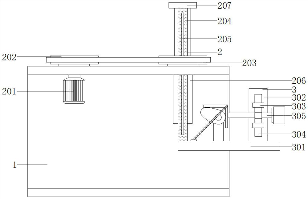
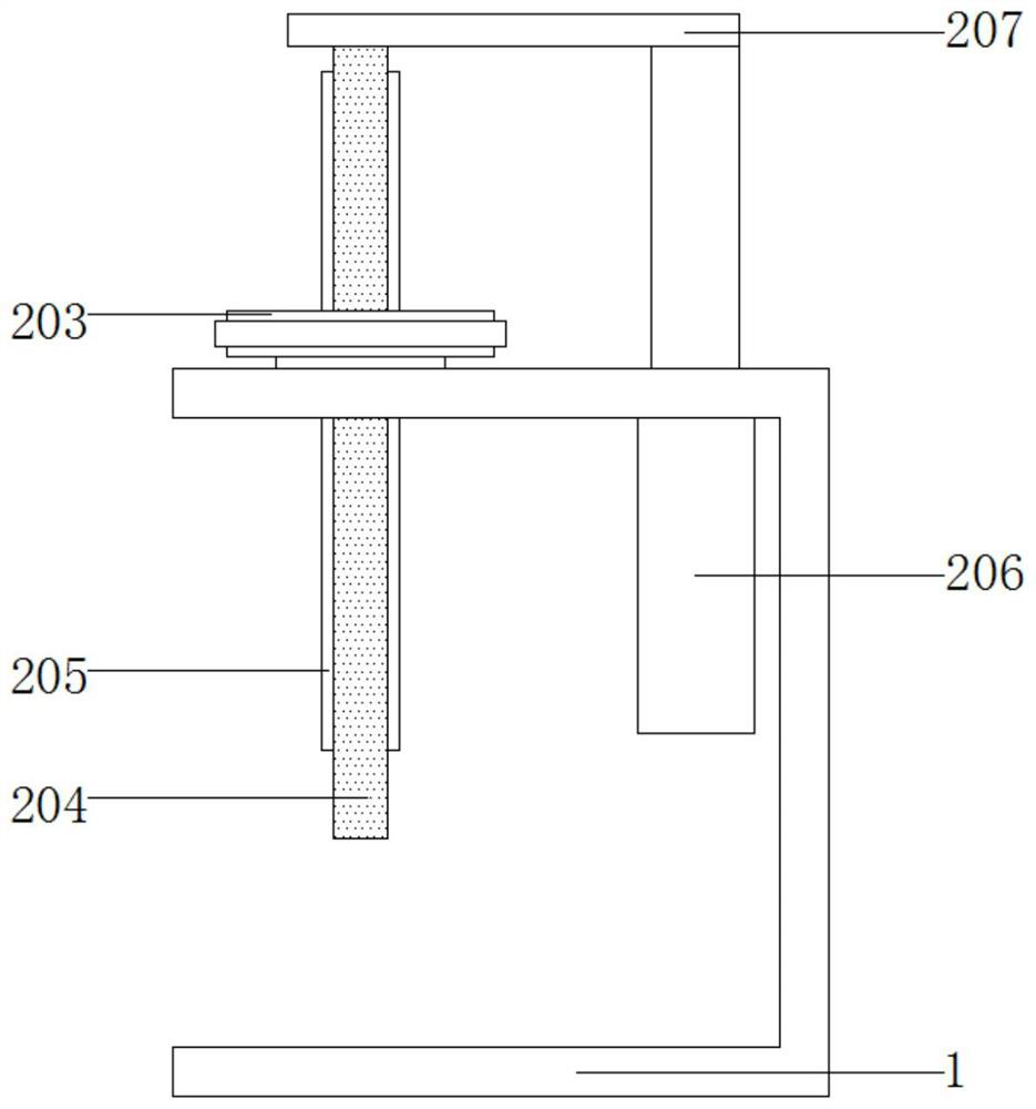
[0026] see Figure 1-2 , an infrared photoelectric intelligent detector, comprising a concave frame plate 1, a rotating telescopic mechanism 2 is arranged above the concave frame plate 1, and the rotating telescopic mechanism 2 includes a first motor 201, a first pulley 202 , the second pulley 203, the moving rod 204, the clip 205, the telescopic rod 206 and the connecting plate 207;
[0027] The upper ends of the concave frame plate 1 are respectively connected with a first pulley 202 and a second pulley 203 in rotation, and the first pulley 202 and the second pulley 203 are connected by a belt drive; A first motor 201 is fixedly connected below, and the first motor 201 is fixedly installed on the upper part of the concave frame plate 1;
[0028] A moving rod 204 is arranged inside the second pulley 203 ; a clip 205 is fixedly connected to the front and rear sides of the moving rod 204 . A telescopic rod 206 is provided on one side of the second pulley 203, and the telescop...
Embodiment 2
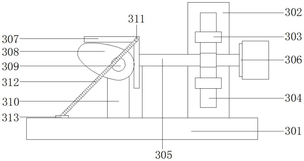
[0031] see figure 1 and image 3 , the bottom end of the moving rod 204 is provided with a moving mechanism 3, the moving mechanism 3 includes a bottom plate 301, a vertical plate 302, a sliding sleeve 303, a sliding rod 304, a guide rod 305, a mounting plate 306, a bending plate 307, a cam 308, the second motor 309, the fixing frame 310, the connecting column 311, the spring 312 and the fixing piece 313;
[0032] A bottom plate 301 is fixedly connected to the bottom end of the moving rod 204 , a vertical plate 302 is fixedly connected above the right end of the bottom plate 301 , and a sliding sleeve 303 is fixedly connected to one side of the vertical plate 302 . A sliding rod 304 is slidably connected, and a mounting plate 306 is fixedly connected to the right end of the sliding rod 304 ; an infrared photodetector is mounted on one side of the mounting plate 306 .
[0033] A bending plate 307 is fixedly connected to the left end of the sliding rod 304, a cam 308 is arrang...
PUM
 Abstract
Description
Claims
Application Information
 - R&D
- Intellectual Property
- Life Sciences
- Materials
- Tech Scout
- Unparalleled Data Quality
- Higher Quality Content
- 60% Fewer Hallucinations
Browse by: Latest US Patents, China's latest patents, Technical Efficacy Thesaurus, Application Domain, Technology Topic, Popular Technical Reports.
© 2025 PatSnap. All rights reserved.Legal|Privacy policy|Modern Slavery Act Transparency Statement|Sitemap|About US| Contact US: help@patsnap.com


