
A kind of gear milling machine which is easy to disassemble the tool

A gear milling machine and cutting tool technology, which is applied to gear cutting machines, gear teeth, manufacturing tools, etc., can solve the problems of low replacement trouble and low efficiency, affecting the production efficiency of gear milling machines, etc., and achieves simple structure, convenient operation, and improved processing efficiency. Effect

Active Publication Date: 2019-11-12
CHONGQING HANYUAN MACHINERY
View PDF7 Cites 0 Cited by
  • Summary
  • Abstract
  • Description
  • Claims
  • Application Information

AI Technical Summary

Problems solved by technology

[0002] Gear milling machine is a kind of equipment for processing gears. Its main function is to mill the gear surface. Before milling the gear surface, it is necessary to install cutting tools on the gear milling machine. Due to the size of the gear And the structure is different, requiring the replacement of different cutting tools. The traditional gear milling machine tool replacement is troublesome and low in efficiency, which seriously affects the production efficiency of the gear milling machine. Therefore, a gear milling machine that is easy to disassemble the tool is needed.

Method used


Image

  • A kind of gear milling machine which is easy to disassemble the tool
  • A kind of gear milling machine which is easy to disassemble the tool

Examples


Embodiment Construction

[0016] The following will clearly and completely describe the technical solutions in the embodiments of the present invention with reference to the accompanying drawings in the embodiments of the present invention. Obviously, the described embodiments are only some, not all, embodiments of the present invention.

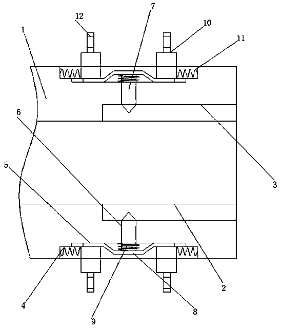
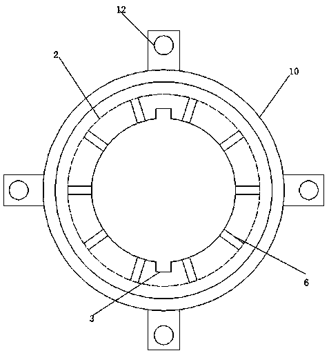
[0017] refer to Figure 1-2 , a gear milling machine for easy disassembly of tools, comprising a cutter head installation shaft 1 installed on the gear milling machine, one end of the cutter head installation shaft 1 is provided with a through hole 2 docked with the cutter head, and the inner wall of the through hole 2 is provided with Two groups of strip-shaped guiding and positioning grooves 3 are arranged symmetrically along the axis of the through hole 2. The outer ring of the cutterhead installation shaft 1 is provided with an arc-shaped installation groove 4 along its axis, and the bottom inner wall of the arc-shaped installation groove 4 is along the The axial...


PUM


Abstract

The invention discloses a gear milling machine facilitating cutter disassembling. The gear milling machine comprises a cutter head installing shaft installed on the gear milling machine, one end of the installing shaft is provided with a through hole in the side in butt joint with a cutter head, the inner side wall of the through hole is provided with two sets of long-strip-shaped guide positioning holes symmetrically arranged along the axis of the through hole, an arc-shaped installing groove is formed in an outer ring of the installing shaft along the axis, the inner wall of the bottom of the installing groove is provided with an annular sliding groove in the axis direction of the installing shaft, the sliding groove is located in the middle portion of the installing groove, the inner wall of the bottom of the sliding groove is provided with a cylindrical channel communicating with the interior of the through in the axial direction of the installing shaft in an arrayed manner, a channel is located in the middle portion of the sliding groove, a movable rod is connected to the interior of the channel in a movably-sleeving manner, a U-shaped elastic sheet is welded to the end, extending into the installing groove, of the movable rod, and the two ends of the U-shaped elastic sheet extend into the sliding groove. The gear milling machine is simple in structure and convenient to operate, a cutter on the gear milling machine can be conveniently replaced, the cutter replacing efficiency of the gear milling machine is improved, and the machining efficiency of the gear milling machine is improved.

Description

technical field [0001] The invention relates to the technical field of gear milling machines, in particular to a gear milling machine which facilitates tool disassembly. Background technique [0002] Gear milling machine is a kind of equipment for processing gears. Its main function is to mill the gear surface. Before milling the gear surface, it is necessary to install cutting tools on the gear milling machine. Due to the size of the gear And the structures are different, requiring the replacement of different cutting tools. The traditional gear milling machine is troublesome and inefficient for tool replacement, which seriously affects the production efficiency of the gear milling machine. Therefore, a gear milling machine that is easy to disassemble the tool is needed. Contents of the invention [0003] The purpose of the present invention is to solve the shortcomings in the prior art, and propose a gear milling machine that is convenient for disassembling the cutter. ...

Claims


Application Information

Patent Timeline
Patent Type & Authority Patents(China)
IPC IPC(8): B23F23/12B23F5/20
CPCB23F5/20B23F23/1237
Inventor 罗昭成
Owner CHONGQING HANYUAN MACHINERY
Learn More