Brake system for a motor vehicle and method for operating a brake system for a motor vehicle

A braking system and a technology for motor vehicles, which are applied in the field of braking systems of vehicles to achieve the effect of good controllability

Active Publication Date: 2018-10-23
AUDI AG
View PDF7 Cites 2 Cited by
  • Summary
  • Abstract
  • Description
  • Claims
  • Application Information

AI Technical Summary

Problems solved by technology

But for this, the driver has to exert greater than usual operating forces on the operating elements

Method used


Image

  • Brake system for a motor vehicle and method for operating a brake system for a motor vehicle

Examples


Embodiment Construction

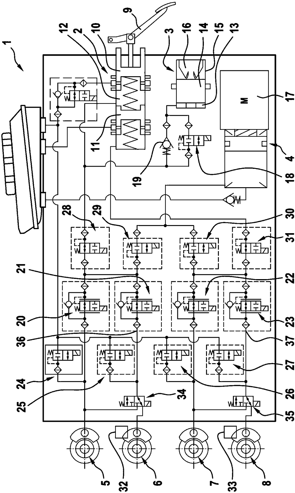
[0034] figure 1 Shows a schematic view of a brake system 1 for a motor vehicle with a master brake cylinder 2 , a brake force simulator 3 , a brake pressure source 4 and wheel brakes 5 , 6 , 7 and 8 . The number of wheel brakes is of course arbitrary. In the exemplary embodiment shown here, four wheel brakes 5 , 6 , 7 and 8 are provided. However, a greater or lesser number of wheel brakes may also be present. In the exemplary embodiment shown, wheel brakes 5 and 7 are assigned to the wheels of a first wheel axle, in particular a front axle, and wheel brakes 6 and 8 are assigned to wheels of a second wheel axle, in particular a rear axle, of the motor vehicle.

[0035] Master brake cylinder 2 is associated with an actuating element 9 , which is designed here as a brake pedal. The operating element 9 is coupled to the main brake piston 10 , for example via a rod connection. Master brake piston 10 is arranged displaceably in master brake cylinder 2 . In the exemplary embodi...


PUM


Abstract

The invention relates to a brake system (1) of a motor vehicle. The brake system for the motor vehicle has at least a first wheel brake (5, 7) and at least a second wheel brake (6, 8). A first inlet valve (20, 22) is fluidically connected, on the one hand, to the first wheel brake (5, 7), and, on the other hand, to a brake pressure source (4), and a second inlet valve (21, 23) is fluidically connected, on the one hand, to the second wheel brake (6, 8) and on the other hand, to the brake pressure source (4). In this case, a switching valve (34, 35) is provided, which fluidically connects the one fluid outlet (36, 37) of the second inlet valve (21, 23) in a first switching position to the second wheel brake (6, 8) and in a second switching position to the first wheel brake (5, 7). Additionally, the invention also relates to a method for operating the brake system for the motor vehicle.

Description

technical field [0001] The invention relates to a braking system of a motor vehicle having at least one first wheel brake and at least one second wheel brake, on the one hand the first wheel brake and on the other hand the brake pressure A first inlet valve is flow-connected to the source, and a second inlet valve is flow-technically connected to the second wheel brake on the one hand and to the brake pressure source on the other hand. Furthermore, the invention relates to a method for operating a brake system for a motor vehicle. Background technique [0002] The braking system is used to decelerate the motor vehicle and thus to provide a braking force acting on the wheels of the motor vehicle. The braking force is applied to the wheels by means of the wheel brakes, namely the first wheel brake and the second wheel brake. In this case, a first wheel brake is provided to apply a braking force to a first wheel, and a second wheel brake is provided to apply a braking force t...

Claims


Application Information

Patent Timeline
Patent Type & Authority Applications(China)
IPC IPC(8): B60T13/10B60T13/66
CPCB60T13/10B60T13/66B60T13/662B60T8/267B60T8/348B60T8/4081B60T8/306B60T8/404B60T8/4072B60T13/588B60T15/028B60T17/083F15B2201/31
Inventor T·布罗克H·恩斯特
Owner AUDI AG
Why Eureka
Try Eureka