Unmanned aerial vehicle parachute system

A technology of drone parachute and parachute, which is applied in the field of UAV parachute system, which can solve the problems of parachute jamming, uneven force on the ejection plate, long effective length of ejection umbrella chamber, etc., and achieve the effect of improving the success rate and reducing the phenomenon of jamming

Pending Publication Date: 2018-10-23
GUILIN UNIV OF AEROSPACE TECH
View PDF12 Cites 11 Cited by
  • Summary
  • Abstract
  • Description
  • Claims
  • Application Information

AI Technical Summary

Problems solved by technology

[0003] The existing rotor parachute ejection chamber mainly uses a single spring to realize the parachute ejection function. When a single spring is ejected, the ejection plate will be stuck due to uneven force on the ejection plate; and, due to the use of a single

Method used


Image

  • Unmanned aerial vehicle parachute system
  • Unmanned aerial vehicle parachute system
  • Unmanned aerial vehicle parachute system

Examples


Embodiment Construction

[0021] The technical solutions of the present invention will be further described below in conjunction with the embodiments shown in the accompanying drawings.

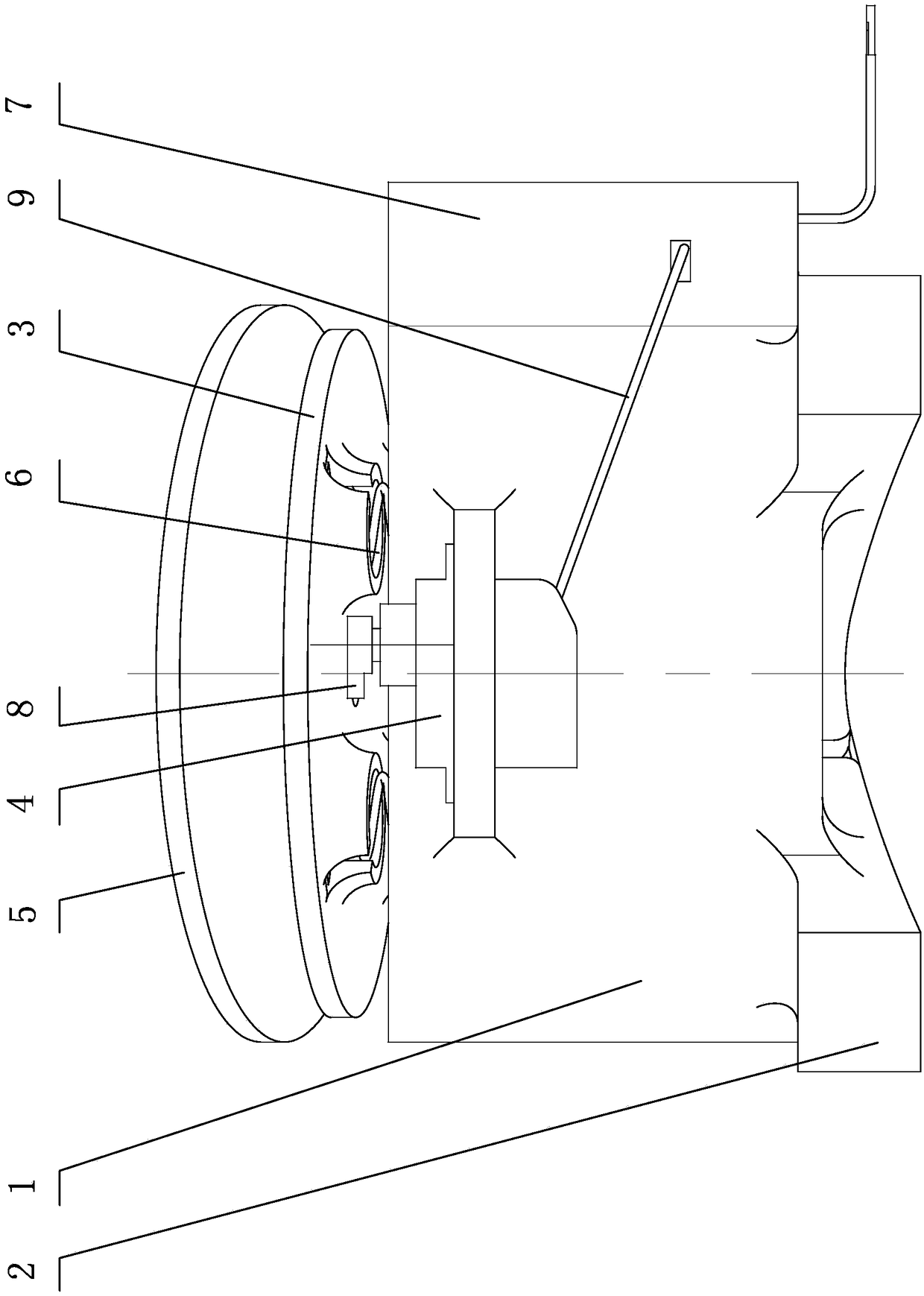
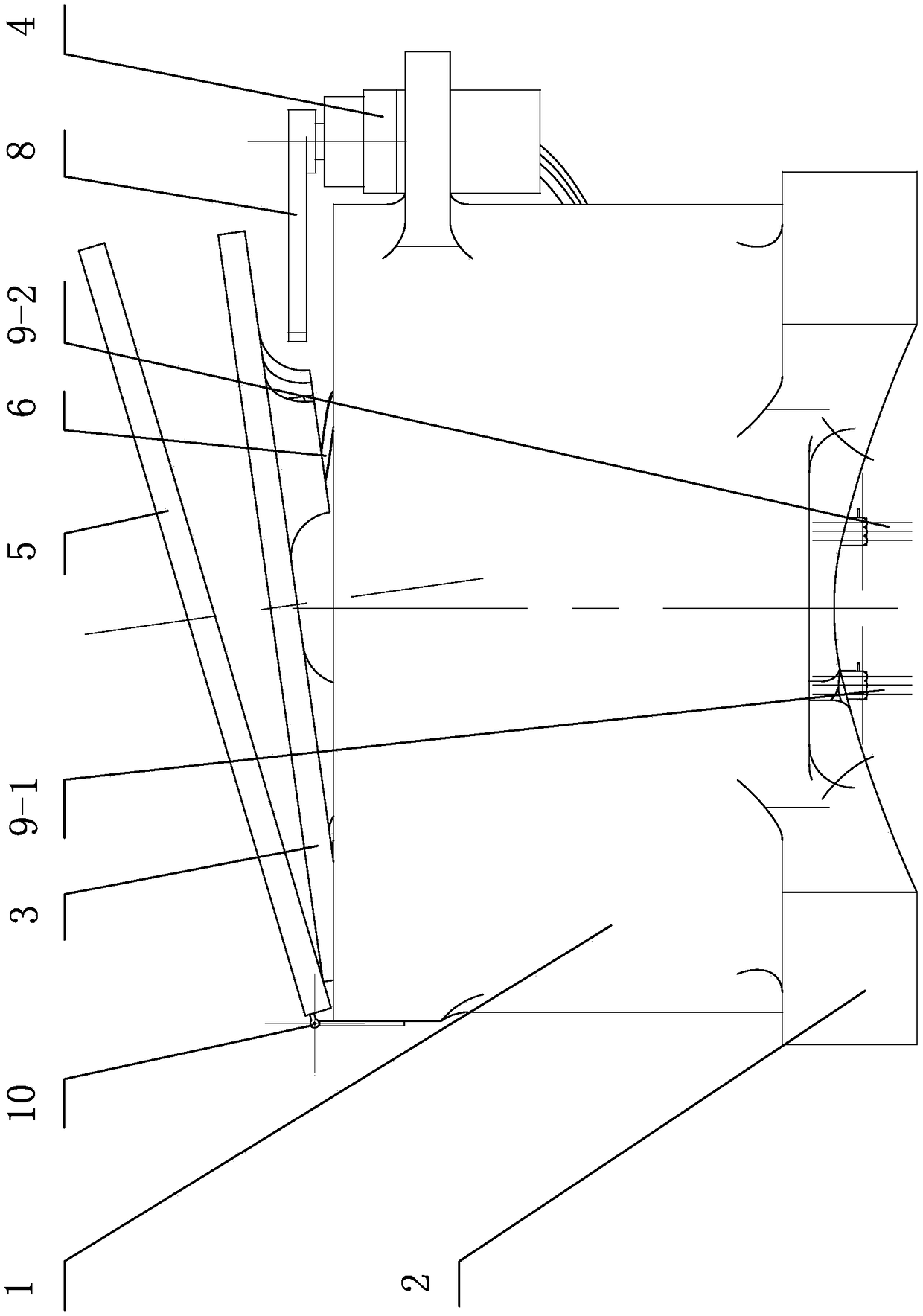
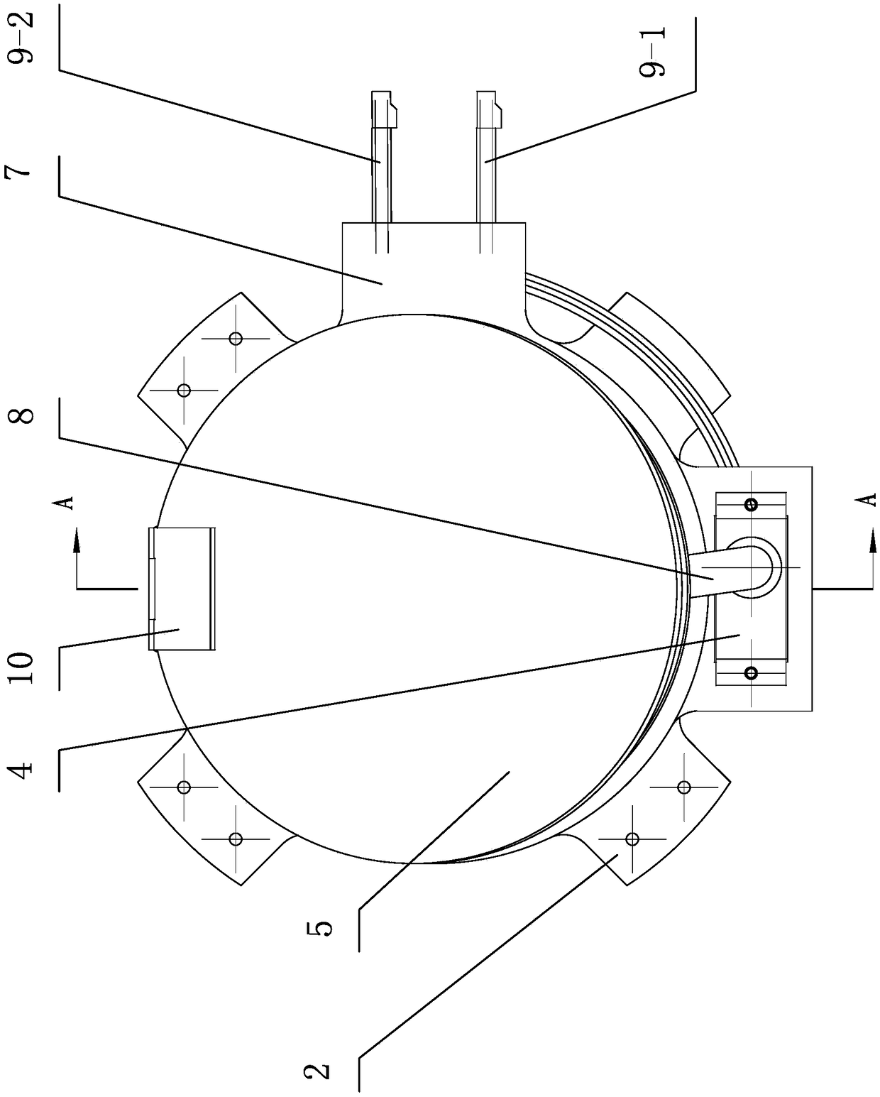
[0022] The UAV parachute system of the present invention comprises a parachute, an ejection umbrella chamber 1, an ejection plate 3, an ejection spring 6 and a steering gear 4.

[0023] The mouth of the ejection umbrella bin 1 is provided with a bin cover 5, the bottom of the ejection umbrella bin 1 is concave and the outer wall of the bottom is evenly distributed with four bases 2, and the ejection umbrella bin 1 is installed by four bases 2. On the frame of the UAV fuselage; one end of the cover 5 is hinged on the opening of the ejection umbrella compartment 1 through a hinge 10, and the steering gear 4 is mounted on the ejection umbrella compartment 1 compartment at the other end of the compartment cover 5 It is fixedly installed on the wall, and the rotating shaft that the steering gear 4 protrudes upwards is equi...


PUM


Abstract

The invention discloses an unmanned aerial vehicle parachute system. The unmanned aerial vehicle parachute system comprises a parachute device; the parachute device comprises a parachute catapulting cabin, a parachute and a catapulting plate; a cabin cover is arranged at a cabin opening of the parachute catapulting cabin, one end of the cabin cover is hinged to the cabin opening, and the other endof the cabin cover is locked and closed at the cabin opening through a parachute opening mechanism; the catapulting plate is mounted to catapulting springs through the locked and closed cabin cover in a pressed mode, wherein the catapulting springs are evenly distributed on the circumference in the parachute catapulting cabin; the folded parachute is arranged between the cabin cover and the catapulting plate; and a parachute rope of the parachute penetrates through a center hole of the catapulting plate to be fixedly connected to the cabin bottom of the parachute catapulting cabin. Accordingto the unmanned aerial vehicle parachute system, the parachute can be catapulted out of the parachute catapulting cabin more quickly, and due to the fact that balance force is adopted to catapult theparachute, the catapulting successful rate can be effectively increased.

Description

technical field [0001] The invention relates to supporting components of an unmanned aerial vehicle (UAV), in particular to a parachute system for an unmanned aerial vehicle. Background technique [0002] At present, the parachute landing system of the rotor UAV mainly adopts the mode of ejecting the parachute from the ejection chamber. After the parachute is ejected out of the ejection chamber, the parachute is opened due to the effects of air resistance, aircraft pulling force and its own gravity, and the parachute generates upward pulling force to the aircraft to protect the aircraft from landing safely. [0003] The existing rotor parachute ejection chamber mainly uses a single spring to realize the parachute ejection function. When a single spring is ejected, the ejection plate will be stuck due to uneven force on the ejection plate; and, due to the use of a single The root spring provides the ejection force, and the effective length of the ejection parachute compartme...

Claims


Application Information

Patent Timeline
IPC IPC(8): B64D17/70B64D17/80
CPCB64D17/70B64D17/80
Inventor 孙山林孙鹏姚钘李云张绍荣谭志诚辛以利谢磊韩一帆
Owner GUILIN UNIV OF AEROSPACE TECH
Why Eureka
Try Eureka