Forward movement type automatic material pushing forklift
What is AI technical title?
AI technical title is built by Patsnap AI team. It summarizes the technical point description of the patent document.
A material fork, automatic technology, applied in the direction of lifting device, etc., can solve problems such as damage and wear of goods, and achieve the effect of accelerating sliding speed, improving utilization rate and easy control.
Active Publication Date: 2018-10-23
ZHEJIANG SHANGJIA MACHINERY
View PDF6 Cites 4 Cited by
Summary
Abstract
Description
Claims
Application Information
AI Technical Summary
This helps you quickly interpret patents by identifying the three key elements:
Problems solved by technology
Method used
Benefits of technology
Problems solved by technology
[0005] The purpose of the present invention is to address the deficiencies of the prior art. By setting the control assembly to move up and down relative to the support assembly, the roller is intermittently in contact with the material, thereby solving the problem of the goods being placed on the bottom surface of the place when the goods are transported to the required position. Contact friction, causing wear and damage to the goods
Method used
Image
Click on the blue label to locate the original text in one second.
Reading with bidirectional positioning of images and text.
Examples
Embodiment 1
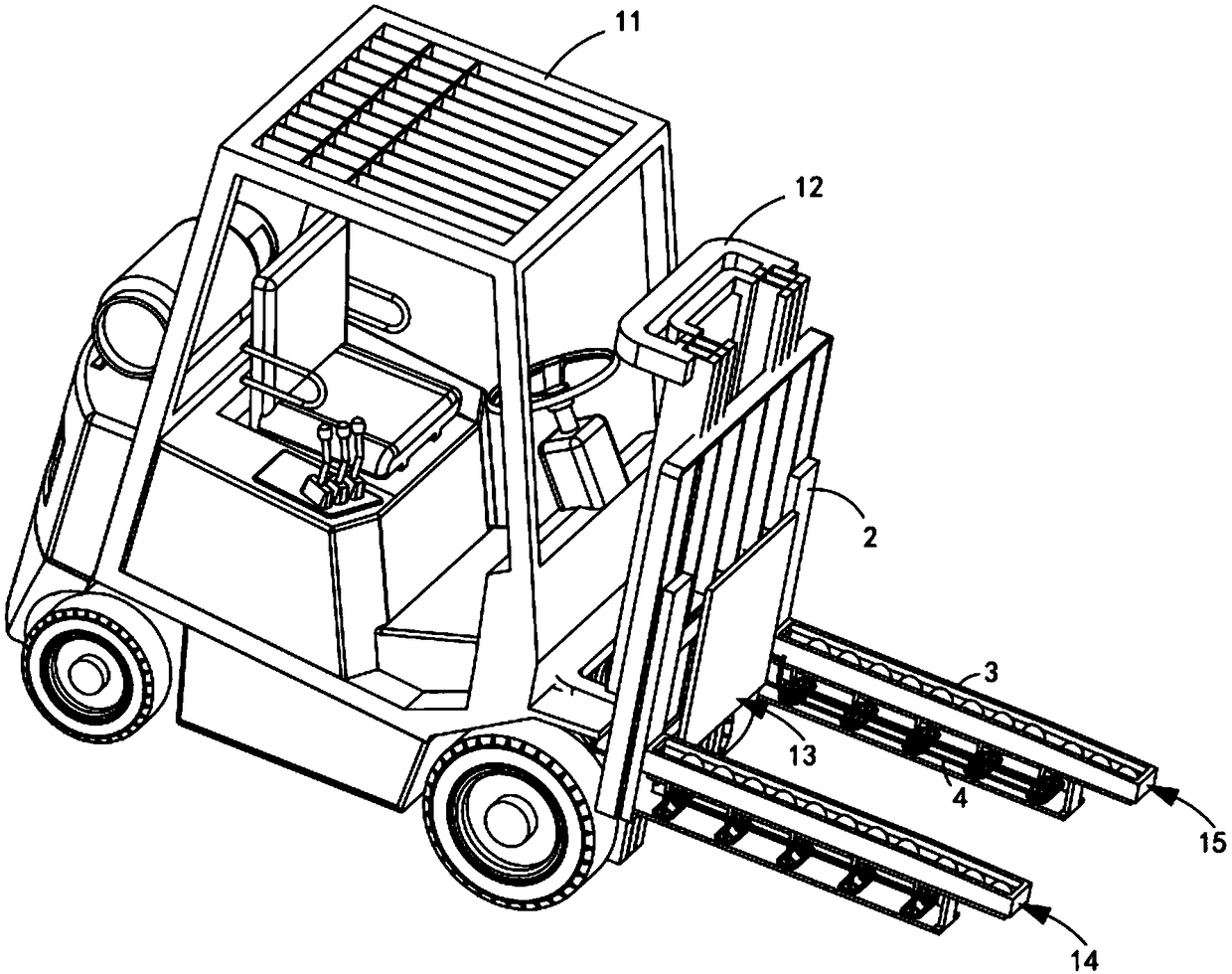
[0067] like figure 1 As shown, a forward-moving automatic pusher forklift includes a forklift 11, a mounting frame 12 arranged in front of the forklift, and also includes:
[0068] A horizontal push mechanism 13, the horizontal push mechanism 13 is installed on the mounting frame 12;
[0069] A lifting mechanism a14, the lifting mechanism a14 is arranged on the mounting frame 12 and is located on one side of the horizontal pushing mechanism 13; and
[0070] a lifting mechanism b15, the lifting mechanism b15 is arranged symmetrically with the lifting mechanism a14;
[0071] Both the lifting mechanism a14 and the lifting mechanism b15 include a support assembly 2 fixedly arranged on the mounting frame 12, a control assembly 3 slidably arranged on the support assembly 2, and a control assembly 3 arranged on the control assembly 3 and used The drive assembly 4 is used to cooperate with the control assembly 3 to move longitudinally. Under the cooperation of the relative transmiss...
Embodiment 2
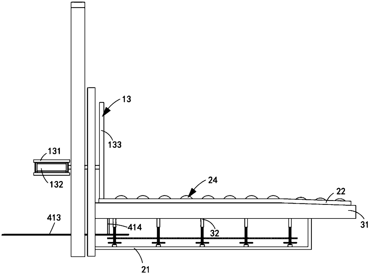
[0114] like figure 2 As shown, the components that are the same as or corresponding to those in the first embodiment are marked with the corresponding reference numerals in the first embodiment. For the sake of simplicity, only the differences from the first embodiment will be described below. The difference between this embodiment two and embodiment one is:
[0115] Further, the rear part of the port 23 of the fixed bin 22 is arranged obliquely downward.
[0116] In the example in this city, the rear part of the bin mouth 23 of the fixed bin 22 is arranged obliquely downward, so that when the material falls to the destination, it plays a guiding role, speeds up the falling speed of the material, and reduces friction.
[0117] work process:
[0118]When the forklift 11 was close to the placement position, the flat push cylinder 132 was started, and the flat push plate 133 moved forward, and the flat push plate 133 began to contact the material. At the same time, the connect...
PUM
Abstract
The invention relates to a forward movement type automatic material pushing forklift. The forward movement type automatic material pushing forklift comprises a forklift, a mounting frame arranged in the front of the forklift, a horizontal pushing mechanism, a lifting mechanism a and a lifting mechanism b, wherein the horizontal pushing mechanism is mounted on the mounting frame; the lifting mechanism a is arranged on the mounting frame and is located at one side of the horizontal pushing mechanism; the lifting mechanism b and the lifting mechanism a are symmetrically arranged; each of the lifting mechanism a and the lifting mechanism b comprises a support component fixedly arranged on the mounting frame, a control component slidably arranged on the support component and a driving componentarranged on the control component and used for matching longitudinal movement of the control component; with cooperation of relative transmission of the control components and the support components,the driving components drive the materials to achieve the smooth transmission in the horizontal direction. Through the forward movement type automatic material pushing forklift, the problem that thegoods are abraded and damaged because of the contact between the goods and the ground of the placement site caused when a later good needs to be used for pushing a former good to work during carryingthe goods to the needed position is solved.
Description
technical field [0001] The invention relates to the technical field of forklifts, in particular to a forward-moving automatic material pushing forklift. Background technique [0002] The fork legs of the existing forklift are articulated on the lifting frame of the forklift. When the goods need to be moved, the goods need to be moved and placed on the fork legs. The lever is used to control the fork legs of the forklift up and down, so that the goods on the fork legs can be moved to the desired position. It is very difficult to adjust the goods being carried left and right. If the goods need to be moved to the left and right positions Accurate placement can only be achieved by relying on the left and right steering of the forklift itself. This adjustment method has high requirements for the operator who controls the forklift and is difficult to grasp. Reduced work efficiency. [0003] Patent No. CN104310279A patent literature discloses a forklift, comprising a forklift bod...
Claims
Application Information
Patent Timeline
Application Date:The date an application was filed.
Publication Date:The date a patent or application was officially published.
First Publication Date:The earliest publication date of a patent with the same application number.
Issue Date:Publication date of the patent grant document.
PCT Entry Date:The Entry date of PCT National Phase.
Estimated Expiry Date:The statutory expiry date of a patent right according to the Patent Law, and it is the longest term of protection that the patent right can achieve without the termination of the patent right due to other reasons(Term extension factor has been taken into account ).
Invalid Date:Actual expiry date is based on effective date or publication date of legal transaction data of invalid patent.

