Optical unit and optical unit with 3-axis shake correction function

An optical unit and optical element technology, applied in optics, instruments, cameras, etc., can solve the problems of large driving force and large power consumption, and achieve the effect of reducing tolerance, reducing power consumption, and suppressing image defects

Active Publication Date: 2018-10-23
SANKYO SEIKI MFG CO LTD
View PDF4 Cites 5 Cited by
  • Summary
  • Abstract
  • Description
  • Claims
  • Application Information

AI Technical Summary

Problems solved by technology

Since this optical unit is a large unit in which the optical module to be rotated includes not only the imaging element but also optical elements such as lenses, a large driving force is required, and the magnetic drive mechanism constituting the roll correction mechanism is enlarged.
In addition, in order to rotate a large unit, the power consumption for driving the roll correction mechanism is large

Method used


Image

  • Optical unit and optical unit with 3-axis shake correction function
  • Optical unit and optical unit with 3-axis shake correction function
  • Optical unit and optical unit with 3-axis shake correction function

Examples


Embodiment Construction

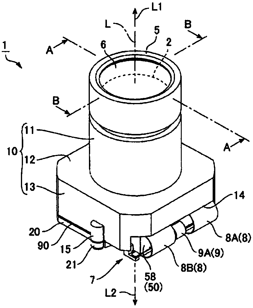
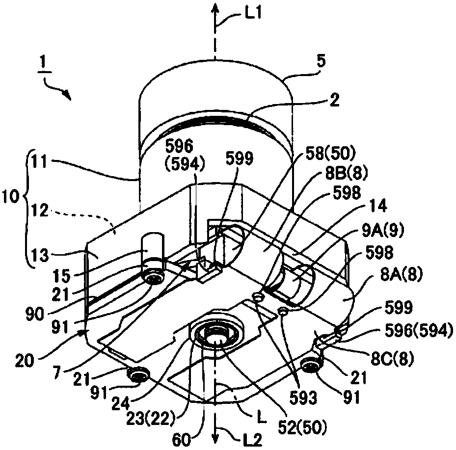
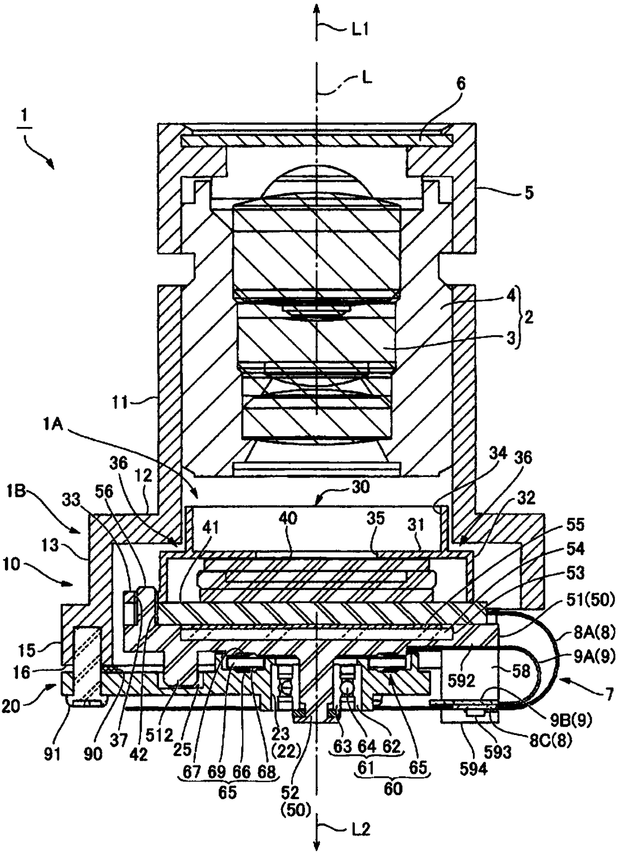
[0163] Hereinafter, embodiments of the optical unit 1 to which the present invention is applied will be described with reference to the drawings. In this specification, the symbol L is the optical axis of the optical unit 1 , the L1 direction is the object side in the optical axis L direction, and the L2 direction is the opposite object side in the optical axis L direction.

[0164] Fig. 1 (a) and Fig. 1 (b) are the perspective views of the optical unit 1 to which the present invention is applied, Fig. 1 (a) is the perspective view observed from the subject side L1, Fig. 1 (b) is the perspective view from the reverse subject Perspective view from side L2. in addition, figure 2 , image 3 It is a sectional view of the optical unit 1 of Fig. 1(a) and Fig. 1(b), figure 2 It is the A-A sectional view of Fig. 1 (a), image 3 It is a B-B sectional view of Fig. 1(a). As shown in FIG. 1(a) and FIG. 1(b), the optical unit 1 includes a lens unit 2, a lens holder 10 as a holder memb...


PUM


Abstract

The present invention provides an optical unit and an optical unit with a 3-axis shake correction function. An optical unit including a roll correction mechanism is miniaturized. The optical unit fixes a substrate on which an imaging element is mounted to a rotating pedestal that is separated from a lens unit and a lens holder, so that the rotating pedestal rotates to perform roll correction. A coil of a magnetic drive mechanism for roll and at least a part of the projection area in the optical axis L direction of the magnet overlap with the substrate on which the imaging element is mounted. Further, since a rotation support mechanism includes a bearing portion and a rotation support portion, and the rotation support portion is disposed radially outside the bearing portion, compared with aconfiguration in which two sets of ball bearings such as the bearing portion are arranged to overlap each other in the optical axis L direction, the thickness in the optical axis L direction is small. Therefore, the optical unit can be miniaturized, and the optical unit can be made lighter.

Description

technical field [0001] The present invention relates to an optical unit that performs roll correction for correcting shake around an optical axis. Background technique [0002] An optical unit mounted on a mobile terminal or a mobile body is provided with a mechanism for correcting shake by swinging or rotating an optical module in order to suppress disturbance of a captured image when the mobile terminal or mobile body moves. Such an optical unit is provided with a swing mechanism for tilting the optical module in two directions of pitching (pitching / tilting) and yawing (rolling / panning). Degrees correspondingly swing in pitch direction and yaw direction. In addition, a roll correction mechanism that rotates the optical module around the optical axis in accordance with vibration around the optical axis is provided. [0003] The optical unit including the roll correction mechanism rotates the optical module including optical elements such as lenses (1ens) and the imaging e...

Claims


Application Information

Patent Timeline
Patent Type & Authority Applications(China)
IPC IPC(8): G03B5/08G03B30/00
CPCG03B5/08
Inventor 须江猛南泽伸司五明正人小松亮二
Owner SANKYO SEIKI MFG CO LTD
Why Eureka
Try Eureka