Power transmission device, power supply system and power reception device
A technology for power supply system and power transmission, applied in circuit devices, battery circuit devices, collectors, etc., can solve cumbersome problems
- Summary
- Abstract
- Description
- Claims
- Application Information
AI Technical Summary
Problems solved by technology
Method used
Image


Examples
no. 1 approach
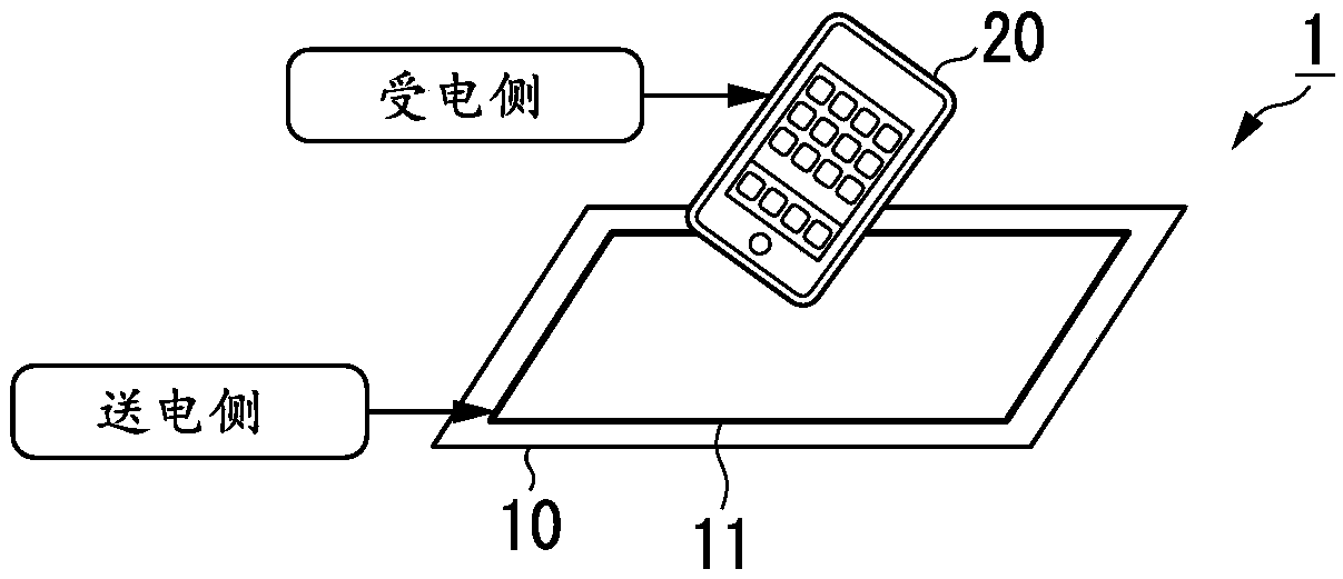
[0027] A first embodiment of the present invention will be described with reference to the drawings. figure 1 It is an external view of the power supply system 1 according to this embodiment. exist figure 1 In the shown example, the power supply system 1 is configured to include a power transmission unit 10 provided on the power transmission side, and a power reception unit 20 provided on the power reception side.
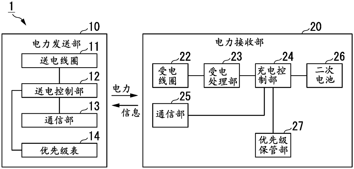
[0028] The power transmission unit 10 is configured as a power transmission device including a power transmission coil 11 that transmits acquired power. The supplied AC power flows through the power transmission coil 11 . Since the intensity of the current varies with time, the intensity of the magnetic field around the power transmission coil 11 varies. This variation is radiated from the power transmission coil 11 as an electromagnetic wave.
[0029] The power receiving unit 20 receives power transmitted by electromagnetic waves when located in the charging a...
no. 2 approach
[0080] Next, a second embodiment of the present invention will be described. About the same structure as embodiment mentioned above, the same code|symbol is attached|subjected, and the description is referred. Figure 6 It is a schematic block diagram of the power supply system 1A according to this embodiment. The power supply system 1A is configured to include a power transmission unit 10 and a power reception unit 20A.
[0081] The power receiving section 20A is in the power receiving section 20 ( figure 2 ) includes a charging control unit 24A instead of the charging control unit 24, and further includes a priority input unit 28A. The priority of the machine itself is input to the priority input unit 28A, and priority information indicating the input priority is stored in the priority storage unit 27 . At this time, the priority information stored in the priority storage unit 27 is updated. The priority input unit 28A may be configured to include an operation device th...
no. 3 approach
[0098] Next, a third embodiment of the present invention will be described. About the same structure as the above-mentioned embodiment, the same code|symbol is attached|subjected, and the description is referred. Figure 9 It is a schematic block diagram of the power supply system 1B according to this embodiment. The power supply system 1B is configured to include a power transmission unit 10B and a power reception unit 20 .
[0099] The power transmission unit 10B is in the power transmission unit 10 ( figure 2 ) includes a power transmission control unit 12B instead of the power transmission control unit 12, and further includes a priority input unit 15B. In the priority input unit 15B, the priority of an arbitrary power receiving unit 20 is input, and priority information indicating the input priority is stored in the priority table 14 in association with the device ID of the power receiving unit 20 . . At this time, among the priority information already stored in the...
PUM
 Abstract
Description
Claims
Application Information
 - Generate Ideas
- Intellectual Property
- Life Sciences
- Materials
- Tech Scout
- Unparalleled Data Quality
- Higher Quality Content
- 60% Fewer Hallucinations
Browse by: Latest US Patents, China's latest patents, Technical Efficacy Thesaurus, Application Domain, Technology Topic, Popular Technical Reports.
© 2025 PatSnap. All rights reserved.Legal|Privacy policy|Modern Slavery Act Transparency Statement|Sitemap|About US| Contact US: help@patsnap.com