
Production line assembly jig

An assembly line and fixture technology, applied in the direction of manufacturing tools, metal processing, metal processing equipment, etc., to achieve the effect of accurate position, easy positioning, and improved operating efficiency

Pending Publication Date: 2018-10-26
SUZHOU RS TECH
View PDF0 Cites 2 Cited by
  • Summary
  • Abstract
  • Description
  • Claims
  • Application Information

AI Technical Summary

Problems solved by technology

[0005] Therefore, the technical problem to be solved by the present invention is to overcome the defect that the spring snap fixture in the prior art can only clamp the workpiece in one direction, so as to provide a multi-directional simultaneous linkage of the workpiece on multiple stations. Line assembly jig for fixing or releasing

Method used


Image

  • Production line assembly jig
  • Production line assembly jig
  • Production line assembly jig

Examples


Embodiment 1

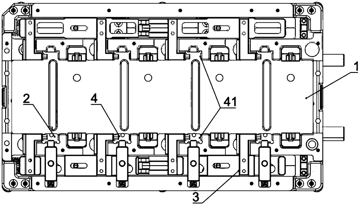
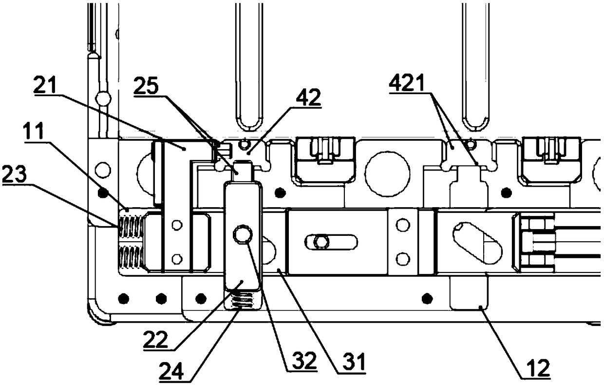
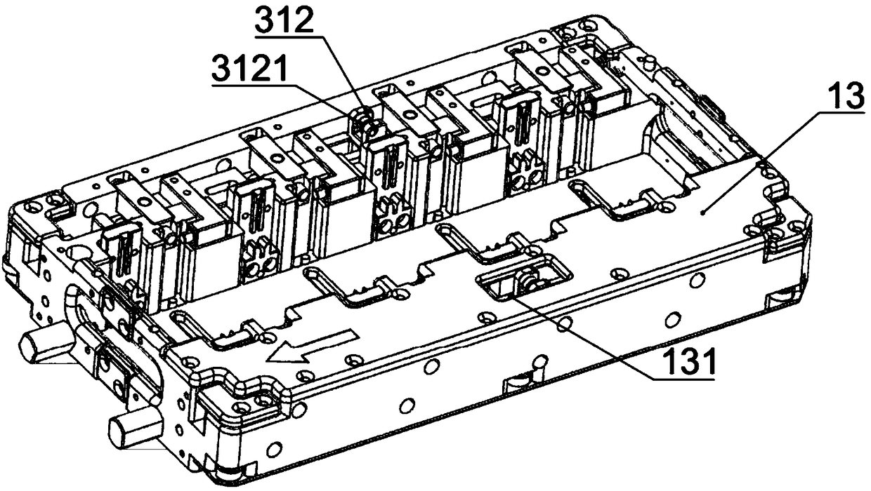
[0043] This embodiment provides an assembly line fixture, its structure is as follows Figure 1 to Figure 4 As shown, it includes a base and several positioning mechanisms and locking mechanisms arranged on the base. The locking mechanism has a locking position for fixing the workpiece and an unlocking position for releasing the workpiece, so that the workpiece placed in the positioning mechanism can be locked at a specific position. Locking is convenient for the positioning of workpieces. It is suitable for assembly line operations. The operating mechanism operates on batches of the same workpieces at the same time, eliminating the trouble of locating the workpieces one by one.

[0044] The locking mechanism 2 in this embodiment includes a traction device 3 and a first locking device 21 connected to the traction device 3 , the traction device 3 is acted by an external force and drives the first locking device 21 to move to an unlocked position or a locked position. At least o...


PUM


Abstract

The invention provides a production line assembly jig. The production line assembly jig comprises a plurality of positioning mechanisms and locking mechanisms, wherein the positioning mechanisms are arranged in a part placing region of a base for initially positioning workpieces. The locking mechanisms are provided with locking positions for locking and fixing the workpieces in the positioning mechanisms and unlocking positions for unlocking the workpieces. The locking mechanisms included draft gears and first locking devices connected to the draft gears, and the draft gears are acted upon byexternal force and drive the first locking devices to move to the unlocking positions or the locking positions; and the locking mechanisms further comprise second locking devices arranged on the draftgears with the first locking devices in a linkage mode. The second locking devices lock the workpieces in a different direction from the first locking devices, and the draft gears are acted upon by the external force and simultaneously drive the first locking devices and the second locking devices to move to the unlocking positions or the locking positions. The production line assembly jig can perform bidirectional positioning on the workpieces and can perform bidirectional locking or unlocking operation at the same time, and is suitable for operation of the workpieces in the production lineoperation.

Description

technical field [0001] The invention relates to the technical field of processing and assembling of electronic components, in particular to an assembly jig for an assembly line. Background technique [0002] Fixture refers to the device used to fix the processing object in the process of mechanical manufacturing so that it can occupy the correct position to accept construction or testing. It is also called fixture. In a broad sense, any process in the process is used to quickly , The device that installs the workpiece conveniently and safely can be called a fixture. The jig usually consists of a positioning element (to determine the correct position of the workpiece in the jig), a clamping device, a tool setting guide element (to determine the relative position of the tool and the workpiece or to guide the direction of the tool), and an indexing device (to enable the workpiece to be installed at one time. It can complete the processing of several stations, including two typ...

Claims


Application Information

Patent Timeline
IPC IPC(8): B23P19/00
CPCB23P19/006
Inventor 吴加富缪磊李预郑俊杰冯小平
Owner SUZHOU RS TECH
Learn More