Bridge pier anti-collision structure

A bridge pier and anti-collision technology, which is applied in bridges, bridge parts, bridge construction, etc., can solve the problems of bridge service life, reduced safety and earthquake resistance, no early warning, monitoring physical anti-collision, and greater safety. Achieve a wide range of market application prospects, strengthen the impact force, and prolong the service life

Pending Publication Date: 2018-10-26
FOSHAN UNIVERSITY
View PDF0 Cites 9 Cited by
  • Summary
  • Abstract
  • Description
  • Claims
  • Application Information

AI Technical Summary

Problems solved by technology

At 5:10 a.m. on June 15, 2007, due to weather conditions, a sand carrier deviated from the main channel and hit the Jiujiang Bridge, causing the bridge deck to collapse about 200 meters. Accident", also known as "Jiujiang Bridge Incident", caused huge casualties and economic losses
Although not every collision accident leads to a major tragedy of bridge destruction, the service life, safety and earthquake resistance of the bridge are definitely reduced, and the economic losses caused by traffic interruption and line repair are also increasing year by year.
[0004] In the prior art, the anti-collision measures for bridge piers are generally to install springs or buffer devices on the bridge piers, and use the principle of spring shock absorption to absorb the impact force when the ship hits the bridge piers, so as to reduce the occurrence of accidents. Although the collision device can reduce accidents, they are all remedial measures taken when the ship collides with the pier. When the ship sails at night, has a large load, and is too fast, there are still major safety hazards, and it is impossible to warn in advance. Monitoring and active and effective physical collision avoidance, so as to provide comprehensive protection for bridge piers and prolong the service life of bridge piers

Method used


Image

  • Bridge pier anti-collision structure
  • Bridge pier anti-collision structure

Examples


Embodiment Construction

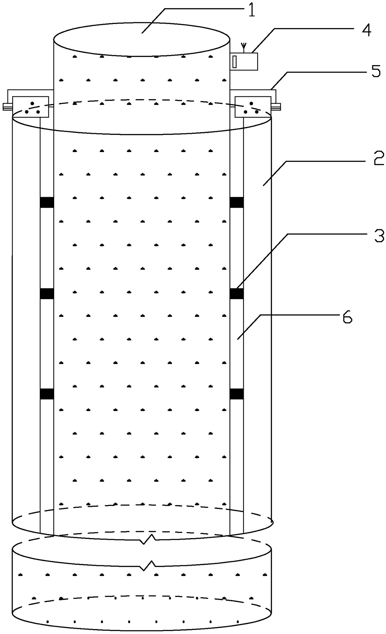
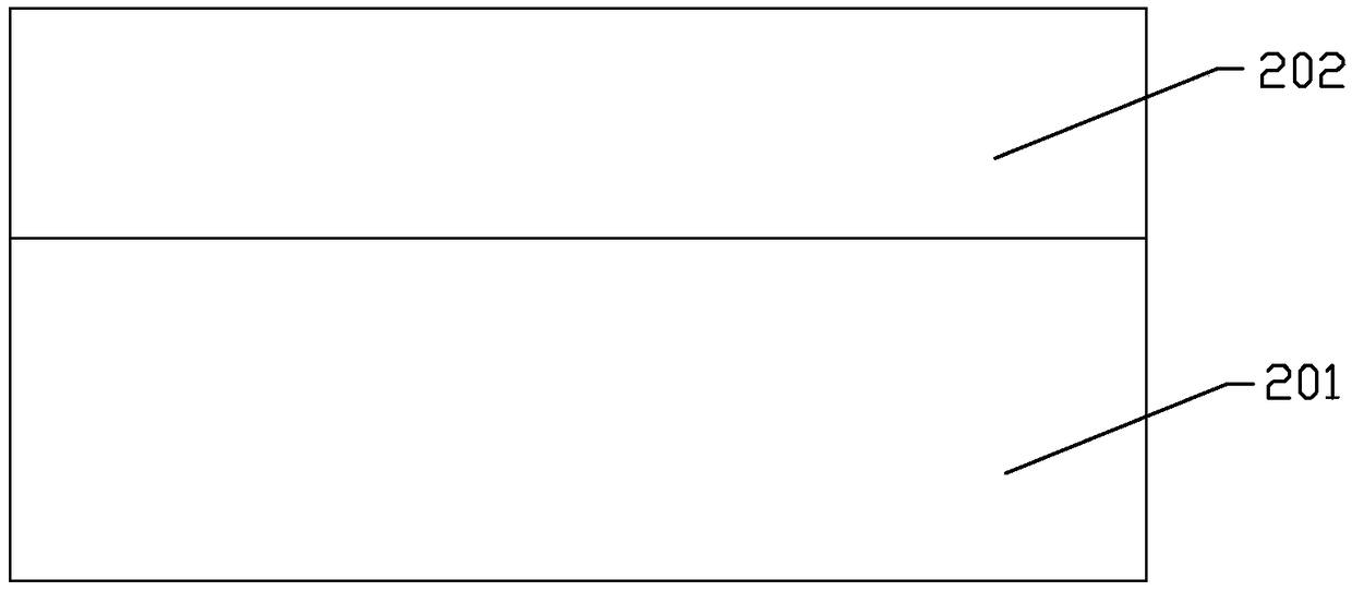
[0020] The idea, specific structure and technical effects of the present invention will be clearly and completely described below in conjunction with the embodiments and accompanying drawings, so as to fully understand the purpose, features and effects of the present invention. Apparently, the described embodiments are only some of the embodiments of the present invention, rather than all of them. Based on the embodiments of the present invention, other embodiments obtained by those skilled in the art without creative efforts belong to The protection scope of the present invention. In addition, all the connection / connection relationships mentioned in this article do not refer to the direct connection of components, but mean that a better connection structure can be formed by adding or reducing connection accessories according to specific implementation conditions. The various technical features in the invention can be combined interactively on the premise of not conflicting wi...


PUM


Abstract

The invention discloses a bridge pier anti-collision structure. The bridge pier anti-collision structure comprises a cylindrical pier and a sleeve arranged outside the cylindrical pier in a sleeving mode. The sleeve wall of the sleeve comprises an outer layer component and an inner layer component which are integrally formed. Idler wheels are arranged on the outer wall of the cylindrical pier. Theinner layer component makes contact with the idler wheels. The sleeve can rotate around the central axis of the cylindrical pier. Through the above design, when a ship collides with the pier, the sleeve rotates, accordingly, the pier forms a guiding inclined angle through impact of the ship, thus direct collision of the ship and the pier is effectively avoided, the collision strength borne by thesleeve is also effectively enhanced, and the great buffer effect on the ship colliding with the ship due to the fact that the ship is out of control can also be achieved. According to the bridge pieranti-collision structure, the maintenance cost of collision between the ship and the pier is effectively reduced, the service life of the pier is prolonged, and the bridge pier anti-collision structure is effective, has wide market application prospects and is worth popularizing energetically.

Description

technical field [0001] The invention relates to the technical field of bridges, in particular to a bridge pier anti-collision structure. Background technique [0002] At present, with the continuous acceleration of my country's infrastructure construction and the vigorous development of the transportation industry, various bridges across rivers and seas have emerged. Due to the heavy weight of the superstructure of long-span bridges, the pressure on the piers also increases. In addition, the lack of anti-collision measures for bridge piers and the misoperation of navigable ships have caused a sharp increase in accidents hitting bridge piers in recent years. Therefore, the anti-collision performance of bridge piers has attracted more and more attention. [0003] In our country, there are many clear cases of ship crashing into bridge accidents. For example, between 1975 and 1999, there were 70 accidents in the Wuhan Yangtze River Bridge, among which there were more than 10 m...

Claims


Application Information

Patent Timeline
Patent Type & Authority Applications(China)
IPC IPC(8): E02B3/26E01D19/02
CPCE01D19/02E02B3/26Y02A30/30
Inventor 黄锐新彭可可吴亚伟陈俊杰马岸民平乐
Owner FOSHAN UNIVERSITY
Why Eureka
Try Eureka